|
|
AUTOCAD ELECTRICAL – WORKING WITH PROJECTS
Autodesk Vault and AutoCAD Electrical Toolset. In a single user environment, a working folder is needed to be set. Start Autodesk Vault Explorer and set a working folder on a local computer and then switch back to AutoCAD Electrical toolset.
AutoCAD Electrical Toolset. Efficiently create, modify, and document electrical controls systems with an industry-specific toolset for electrical design.
Project Manager Panel: To open the Project Manager Panel —» start AutoCAD Electrical —» + (new drawing) —» select Project tab —» in Project Tool Panel select Manager. A project is a set of interrelated electrical drawings. A project file lists the AutoCAD drawing file names that make up the drawing set. Many projects can be creates as you wish, but only one project is active at a time. 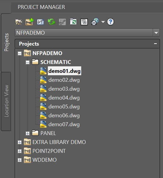
Open a Project: Project Manager —» select Open Project icon —» DC a Project folder —» select .*wdp file —» Open —» select the Project from Project Manage —» RMC —» select Activate —» RMC —» select Expand All (to see the Project's details) —» RMC —» select Flip DWG to Lower/Upper Case (change drawings to upper case or vice versa) —» RMC —» Collapse All (minimize the tree) —» select Drawing List Display Configuration icon (to remove File Name) —» select File Name —» click « to remove File Name —» select Location (if location is preferably) —» click » to add Location Code —» select Sheet Number (if preferably) —» click » to add Sheet Number —» Drawing Description 1 (global default is folder name) —» Drawing Description 2 (global default is location code) —» select Drawing Description 3 (location) —» click » to add Desc. 3 (drawing number becomes DRAWING LIST) —» OK. Note: Updated drawings are now listed with Location + Description.
Open a Drawing: Project Manager —» select a Project —» select a drawing from the Project —» switch to Model Space —» select a component —» RMC —» select Surfer —» the popup window is displaying where this component is on other page —» select Goto will open the drawing that has the selected component —»
Activate a Project: From Project Manage tree —» select a folder —» RMC —» select Activate —» close the present drawing before open a drawing from actived project.
Drawing Sorting in Project Manager: From Project Manage tree drawing can be moved up and down using mouse select/hold/drag and drop. To corrrect and sort —» select the folder —» RMC —» select Sort —» Primary sort select SEC —» Secondary sort select SUBSEC —» Third sort select SUBSEC —» Fourth sort select FILEPATHANDNAME —» OK to sort the drawing back to where it was sequentially. The un-wanted drawing can be remove using RMC and select Remove to remove from the project but not to delete the drawing.
SPONSORED CONTENT

Robot Shop

Revolution Technologies

Your Logo & Brand

Trace Parts
Robot Shop: The easiest way to source custom parts. Get your parts quote and delivery from our network. Production and prototype 3D printing, CNC machining, CNC turning, Surface finishing parts. Sheet-metal fabrication and part marking. Tel: 845-402-8321.
Elite Nationwide Staffing & Solutions. Revolution Technologies headquartered on the Space Coast of Florida in Melbourne connects talented people with career opportunities, while providing clients with premier HR, payroll, consulting services, and workforce solutions.
3D Models & It's Free. Publish your CAD models. If you are a part manufacturer or a part distributor, TraceParts 3D Digital Product Marketing can really work for you! Join hundreds of Part Vendors who already publish their 3D product catalogs with TraceParts to generate thousands of sales-ready Leads.
Support us and grow your business with us. My goal was to make technical information available with ready access to commonly needed resources, formulas, and reference materials while performing my work as a Technical Support Engineer. The businesses listed in Sponsored Content were carefully selected because of their uniqueness. However, non-sponsored ads will be rotated monthly. If your company is interested in placing the company’s logo, brand, event invitation, and other promotional banners and flyers here or on any other pages, please reach out to Customer Service for more detail.
Exception List: From Project Manage tree —» select a Project —» RMC —» Exception List (to see drawings in the project are not listed to match the Project Default) —» OK to close —» select the Schematic folder —» RMC —» Apply Project defaults (to correct the drawings that are not matched the Project default —» select the Project folder —» RMC —» Exception List (to see if there is any drawings left in the project are not listed to match the Project Default) —» OK to close —» Any drawings that are outside Schematic Diagram folder should not be defaulted to its.
Drawing List Report: From Project Manage tree —» select a Project —» RMC —» Drawing List Report —» select Format and pick a report format (.*set) —» OK —» select New Report —» select DoAll —» OK to create reports —» select Put on Drawing —» Table Style select a Style —» Title check Include title line —» type DRAWING LIST (this is the Drawing List drawing in the project folder) —» select Layer —» select Annotation —» OK —» OK to generate Drawing List report. This Drawing List is also coming from .*wdpn file.
Publishing a Project: From Project Manage tree —» select a Project —» RMC —» Publish —» select Publish to PDF/DWF/DWFx —» select DoAll —» OK —» check First layout tab + Multi-sheet file + Include Bookmarks + Include Parent-Child Hyperlinks —» Publish type select PDF —» Zoom factor = 50% —» OK to publish —» Close —» Publish —» File name = Project name —» Select —» Save the current list of sheets? —» select No.
What is .wdp File Association? Project file created by AutoCAD Electrical, a program used for creating wiring diagrams; contains a plain text listing of wire diagram drawing files that together comprise the overall diagram; also contains project settings. Notes: These information form Drawing Properties window will not be available when copied to a new project because they are stored in wdp file not in the drawings. Also, other settings like Drawing Format, Styles, Cross-Refernces, File Numbers, and Components are not copied over to new project. Therefore, do not edit the wdp file. This wdp and aepx are stored in the project folder on company network drive.
Drawing Properties: Select a drawing from Project tree —» RMC —» select Properties —» select Drawing Properties —» Information in Description 1, 2 3 and Section, Sb-section are stored in wdp file.
Components: —» are stored in wdp file.
Wire Numbers: —» are stored in wdp file.
Cross-References: —» are stored in wdp file.
Styles: —» are stored in wdp file.
Drawing Formats are stored in wdp file.
What is .aepx File Association? Created by the program, these files provide various functions such as keeping a project consistent, helping update custom title blocks across a project, or providing custom settings for various tools such as the PLC I/O module insertion tool. Do not edit or delete this file.
Support files that can be maintained. Create a Company Data folder next to Project folder on the network. In this floder create folders Catalogs, Circuits, Library, Reports, Support, and Templates.
SUPPORTS FILES THAT HELPS IN ELECTRICAL DESIGN
Support Folder: The files in this folder can be edited using Notes.
‹•› default.inst: Installation code selection list (default.inst) to keep employees using the same codes throughout projects. In an open drawing —» select a component —» RMC —» select Edit Component —» select Project tab from Installation code —» check Include external list —» select an installation code —» OK —» 
‹•› default.loc: Default location lists the default location codes to keep employees using the same codes throughout projects. In an open drawing —» select a component —» RMC —» select Edit Component —» select Project tab from Location code —» check Include external list —» select a location code —» OK —» OK —» select Yes-Update —» select Task —» select Always QSAVE to update —» select a drawing —» —» select Properties —» select Drawing Properties —» here Instaaltion Code and Location Code can be selected using Project tab.
‹•› default.wdt creates a default mapping file in the default AutoCAD Electrical support folder. This file is used if a project-specific file does not exist and no DEFAULT. WDT file exists in the project folder. Drawing Title Block and Description.
‹•› wd_desc.wdd To view a Description File select a drawing —» switch to Model Pace —» select a component —» RMC —» select Edit Component —» select Default to view wd_desc.wld file —» Cancel
‹•› default_wdtitle.wdl Drawing Title Block Default Descrription file stored in the default AutoCAD Electrical support folder. This file is used if a project-specific file does not exist and no DEFAULT. WDT file exists in the project folder. To view a Description File select a drawing —» switch to Model Pace —» select a component —» RMC —» select Edit Component —» select Default to view wd_desc.wld file —»
‹•› wd_fam.dat: Family Code (ex: STD, STAN for standard, PW, PS for power). Close AutoCAD after edited this file. 
Search Path to Work with Company Data: Default file search is to check ACAD path first (Schematic Libraries, Panel Footprint Libraries) if not found then Alternate catalog mdb file, if not found then Support file search path. To edit the search path —» goto C:\Libraries\Documents\Acade 2018 or 2019 —» double click (DB) to open —» DC AeData —» select wd.env and rename as wd.env.bak or delete to make one unique wd.env for easy maintaince as long as there is a wd.env file on company network in folder Company Data\Support\ —» select wd.env —» RMC to open with —» select NotePad —» at the bottom of the file, setup a section for the company —» see the right image —» Save —» Close AutoCad and Re-open for the changes to take place.
Create a Title Block in AutoCAD Electrical: First, start a blank new drawing —» draw the drawing border using the same method in standard AutoCAD —» enter ATTDEF to insert attribute definition objects (when the border drawing is inserted as a block on another drawing, attribute definition objects become attributes) —» enter tag name (ex: DESC1, DESC2, SHEET, SHEET_TOTAL, etc.) —» set attribute definition properties and values —» OK to create —» select an insertion point —» repeat for each attribute definition for the title block —» save the border drawing as DWG file.
CREATING NEW PROJECT METHODS
Create a New Project from an Active Project: Project Manager Tree —» select icon New Project —» Input Name —» Location (leave as default) —» Create Folder with Project Name (leave as default) —» Copy Settings from Project File (remove if copied from active project) —» OK to create —» select the Project Name —» RMC —» select Properties —»
Create a New Project from a Selective Project: Project Manager Tree —» select icon New Project —» Input Name —» Location (leave as default) —» Create Folder with Project Name (leave as default) —» Copy Settings from Project File —» select Browse —» select a Project to copy from —» select the *.wdp file —» Open —» select Description tab —» fill out the Title Block form —» OK to create —» select OK-Properties tab to view the copy settings —» OK to close. Note: This method only copy the project settings not the file structure and the drawings.
Copy a Drawing to New Project: Goto Window Explore —» select a Project (source) —» select a drawing from the Project —» RMC —» Copy —» select a Project (destination) —» RMC —» Paste —» in Project Manage select a Folder (destination) —» RMC —» select Add Drawings —» select the drawing —» Add —» Yes to apply project default to drawing settings —» Yes to update terminal associations —» close the drawing to add description —» in Project Manager select the added drawing —» RMC —» select Rename —» change the drawing number —» select the drawing —» RMC —» Open —» select the drawing from Project Manager —» RMC —» Properties —» Drawing Properties —» select Drawing Settings tab —» select Desc. 1 dropdown arrow —» select Schematic Diagram —» select Desc. 2 dropdown arrow —» select a Function description —» select Desc. 3 dropdown arrow or Pick» —» select Schematic Diagram —» pick a description 3 for the Title Block —» Section/Sub-Section (use dropdown arrow to select) —» OK to update —» select drawing Sheet 1 under Schematic Diagram folder —» select Project-Wide Update or Retag —» check Component Retag + Component Cross-Reference Update + Wire Number and Signal Tag/Retag (click Setup to select what needed to update) + Sheet + Resequence - Start with (enter 1) + Title Block Update —» click Setup to select what to update in Title Block —» OK to update —» click DoAll —» OK —» Fileset —» when done click Refresh —» select the next folder in the Project (Single Line Diagram) —» select a drawing to update location and switch to ModelSpace —» select Location —» RMC —» Edit Location Box —» Installation —» select Browse —» External List select a location —» OK —» OK —» Yes-Scan and Update —» Task —» select Project Task Lists from Project Mamager —» Select All —» OK to update all the changes. Note: Always run the Task List everytime after making changes.
NỘI DUNG TÀI TRỢ

Custom Parts Manufacturer

Optics Cable Assemblies

Your Promotion Ads

Linking Talent to Technolgy
The Hubs Manufacturing International Network: The easiest way to source custom parts. Get your parts quote and delivery from our network. Production and prototype 3D printing, CNC machining, CNC turning, Surface finishing parts. Sheet-metal fabrication and part marking. Tel: 845-402-8321.
PTECH Solutions offers off-the-shelf and customized cables, complex harnesses, and electro-mechanical interconnects for all industries. Fiber Optic & Copper Cable Assembly, Mechanical Design, Machined & Sheet-Metal Parts, Gaslines & Weldment Manufacturing, PCB Design & Layout, & Box Build. Tel: 888-207-0646.
Ryzen Solutions is a top engineering/CAD automation and IT staffing agency based in Silicon Valley. Join Ryzen where you can make an impact. Ryzen takes pride in connecting talented individuals to their dream jobs and bringing success to their teams.
Adding a Sub-Folder to the Project: Project Manager Tree —» select a Project —» RMC —» select Add Subfolder —» name the Subfolder. These subfolders are not the same as Window Subfolder. Therefore, there is no Subfolder in Window Browser. Use the same method to create Subfolder under Subfolder.
Adding Drawings to the Folder/Sub-Folder: Project Manager Tree —» select a Folder —» select New Drawing icon —» input Drawing File Name —» Template (leave as default) —» OK to create.
Remove Unwanted Folders: Project Manager Tree —» select a Project —» RMC —» select Flatten Structure —» select Yes to remove all folders in the project —» Template (leave as default) —» OK to create.
Create a Project with a Copy From Another Project: Project Manager Tree —» select a Project to copy —» RMC —» select Flatten Structure —» select Yes to remove all folders in the project —» Template (leave as default) —» OK to create. Note: Do not use the Copy command from Project Tools Panel, this command is only works when all drawings are closed from other users.
Create a New Project Using the Copy Command: With all drawings closed from all users this is the method to create A NEW PROJECT —» Project tab —» Project Tools —» select Copy —» goto Project Manager tree —» select a Project and activate —» Copy Active Project —» select Browse —» select the Project —» select .*wdp file —» Open —» OK —» create a folder —» create a File Name inside the folder —» Save —» select Drawings to process —» select Process —» select Fileset —» Note: select DoAll will copy all drawings in the Project —» select project-related files to be copied (this step is un-neccessary if there is a company Global setting default) —» OK to copy —» select Find/Replace to change the project number —» Find (input the copied number) —» Replace (input a new number) —» OK —» OK to update —» select the Project from Project Manager tree —» RMC —» select Description —» update the Title Block information —» check reports where is needed —» OK to update —» select the Project from Project Manager tree (create a new drawing) —» New Drawing icon —» input Drawing File Name —» Template (global=default or browse) —» Description (input drawing descriptions) —» Sheet (enter 1 for sheet 1) —» Drawing (input drawing number) —» Section/Sub-Section (skipt this option if it's for the entire project, meaning this drawing should be in the Project folder not Sub-Folder) —» OK to update —» Yes to apply. Note: If the created drawing landed in the wrong folder, just drag and drop it to the correct Project folder.
Delete a Project (.*wdp & drawings only): Project Manager Tree —» select a Project tab —» Project Tools —» select Delete —» DC on a Project —» select *.wdp to delete —» Open —» check Delete "wdp + Delete a project's —» Delete Files. This method only delete *.wdp and drawing files, folder and other files are left intact.
Delete a Project: Close the project from Project Manager Tree —» goto window browser —» select a Project folder —» Delete. This method will wipe out the Project completely.
Footprint Database: AutoCAD Electrical uses the footprint database to identify the footprints corresponding to the MANUFACTURER, CATALOG, and ASSEMBLYCODE attribute values of the schematic symbols. Footprint information is furnished with the default AutoCAD Electrical installation. The information is in tables in a Microsoft Access database file (mdb) and the database content is found at C:\Users\{username}\Documents\Acade {version}\AeData\{language code}\Catalogs\.
Insert WBlocked Circuit: Schematic tab —» Circuit Clipboard Panel —» select Copy Clip —» select the basepoint
AUTOCAD ELECTRICAL WD_M FILE
WD_M Block: The WD_M.dwg is found in the default symbol library.  Here is an attribute list of information that is carried on the WD_M block of the drawing, sorted by category: XREFTYPE (System Variable), 0 —» Attachment is the default. 1 —» Overlay is the default.
‹•› XREF_STYLE: —» Circuit Clipboard Panel —» select Copy Clip —» select the basepoint
‹•› XREF_FLAGS: —» Circuit Clipboard Panel —» select Copy Clip —» select the basepoint
‹•› XREF_UNUSEDSTYLE: —» Circuit Clipboard Panel —» select Copy Clip —» select the basepoint
‹•› XREF_FILLWITH: —» Circuit Clipboard Panel —» select Copy Clip —» select the basepoint
‹•› XREF_SORT: —» Circuit Clipboard Panel —» select Copy Clip —» select the basepoint
‹•› XREF_TXTBTWN: —» Circuit Clipboard Panel —» select Copy Clip —» select the basepoint
‹•› XREF_GRAPHIC: —» Circuit Clipboard Panel —» select Copy Clip —» select the basepoint
‹•› XREF_GRAPHICSTYLE: —» Circuit Clipboard Panel —» select Copy Clip —» select the basepoint
‹•› XREF_CONTACTMAP: —» Circuit Clipboard Panel —» select Copy Clip —» select the basepoint
‹•› XREF_TBLSTYLE: —» Circuit Clipboard Panel —» select Copy Clip —» select the basepoint
‹•› XREF_TBLTITLE: —» Circuit Clipboard Panel —» select Copy Clip —» select the basepoint
‹•› XREF_TBLINDEX: —» Circuit Clipboard Panel —» select Copy Clip —» select the basepoint
‹•› XREF_TBLFLDNAMS: —» Circuit Clipboard Panel —» select Copy Clip —» select the basepoint
‹•› XREF_TBLCOLJUST: —» Circuit Clipboard Panel —» select Copy Clip —» select the basepoint
‹•› WNUM_OFFSET: —» Circuit Clipboard Panel —» select Copy Clip —» select the basepoint
AUTOCAD ELECTRICAL TIPS
Editting Revision Block: Open a drawing and select ModelSpace —» select the Revision Block —» Layout tab select Edit Attributes —» edit #REV_NO + #BUN_REV_CREATED_ON_3 + #BUN_REV_CREATED_BY_3 + #BUN_REV_NO_3 (type in value for each selection and select Aplly to update) —» OK —» Zoom All —» switch back to PaperSpace.
Connectors, Point to Point Wiring Diagrams: Open a drawing and select ModelSpace —» select the Revision Block —» Layout tab select Edit Attributes —» edit #REV_NO + #BUN_REV_CREATED_ON_3 + #BUN_REV_CREATED_BY_3 + #BUN_REV_NO_3 (type in value for each selection and select Aplly to update) —» OK —» Zoom All —» switch back to PaperSpace.
Insert Wire Number: Schematic tab —» Insert Wires/Wire Numbers panel —» Insert Wire Numbers drop-down —» Wire Numbers —» select Find —» select to tag all wires or only new wires —» select to process and tag wires with sequential wire numbers or with wire numbers based on the line reference location of the wire network —» specify the wire tag format + the wire layer format + force all wire numbers to be fixed + update cross-reference text on wire signal source and destination symbols + update the database for wire signal source and destination symbols —» select to tag the selected wires, wires on drawing, or wires in a project.
Replacing Company Logo in Title Block: Open a drawing and select ModelSpace —» select the Title Block —» RMC —» select Block Editor —» select the logo and delete —» ADC (Design Center) —» Enter —» goto the folder where to get a replace logo —» select the logo and RMC —» Copy —» X to close ADC —» click where to attach the image and Ctrl+v to paste —» click to select insertion point —» LMC to size —» Enter to accept —» Enter to accept or enter value to rotate —» select te image corner and drag to size —» M (Move) and select the image —» move to new location and click —» Close Block Editor —» Save the changes —» Zoom all —» activate PaperSpace.
Your Support Can Help Us Grow. Thank you for visiting ViBa Direct. As part of our commitment to continually improving the visitor experience, we’re doing our best to add the latest information with ready access to commonly needed resources, engineering, formulas, reference materials, photography, and travel. Unfortunately, we don't have enough manpower to meet everyone's needs. But if you are interested in helping us with the site maintenance cost. Please mail your donation to ViBa Direct., P.O. Box 1801., Pflugerville, TX 78691. Thank you for taking the time to read this. Feel free to Customer Service with any additional feedback you would like to share about your experience visiting ViBaDirect.com


