|
|
AUTOCAD TIPS and GD&T TOOLS
'Open File' window is missing. When select 'File Open' the window where to select the folder and filename is missing, only the Command line is avalable. at the command prompt type FILEDIA —» enter —» type 1 —» enter.
The Status Bar (Bottom Right Graphic Toolbar):
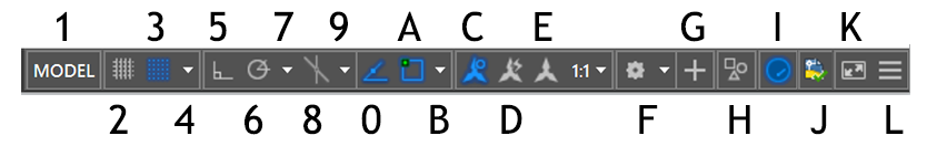
‹•› 1: Toggle between Model and Paper space. In model space, click this button to display the most recently accessed layout. In a layout, click this button to switch from model space in a layout viewport to paper space.
‹•› 2: GRIDMODE: Display drawing grid On/Off (F7) —» to displays a grid in the drawing area.
‹•› 3: SNAPMODE: Snap to drawing grid On/Off (F9) to snap to (model) drawing grid. Grid can not be turned On/Off in Drawing mode.
‹•› 4: SNAPMODE —» to select Polar Snap, Grid snap On/Off and Snap setting (F9). When polar snaps are turned on, the cursor snaps to specified distances along specified polar alignment paths.
‹•› 5: ORTHOMODE —» Ortho mode On/Off (F8) to constrain (bị hạn chế) cursor movement to the horizontal or vertical direction. Ortho mode is used when you specify an angle or distance by means of two points using a pointing device. In Ortho mode, cursor movement is constrained to the horizontal or vertical direction relative to the UCS. Occasionally, Ortho Mode and object snaps interfere with drafting in AutoCAD. Disabling them as to keeps them from being a problem.
SPONSORED CONTENT

Your Service Flyer

Your Event Invitation

Your Promotion Ads

Your Logo & Brand
Support us and grow your business with us. My goal was to make technical information available with ready access to commonly needed resources, formulas, and reference materials while performing my work as a Technical Support Engineer. The businesses listed in the Sponsored Content section were randomly selected because of their uniqueness. However, non-sponsored selected ads will be rotated monthly.
Viba Direct lacks an advisory board to do research and hire writers with the latest technological knowledge. Creating an effective advisory board requires more than an invitation. Without your sponsorship, this is not possible. If your company is interested in placing the company's logo, brand, event invitation, and other promotional banners and flyers here or on any other pages. Please Customer Service for more detail.
‹•› 6: Polar Tracking —» Polar tracking On/Off (F10).
‹•› 7: Polar Tracking —» Polar tracking Settings (F10). Restrict cursor to specified angles "to tracks the cursor along specified (ex: 90, 180, 270, 360) polar angles".
‹•› 8: ISODRAFT —» Isometric Drafting or Orthographic drafting. —» to simulate an isometric drawing by aligning objects along isometric axes, where angle between each axis is 120°.
‹•› 9: ISODRAFT —» Isometric Drafting —» to select an Isometrci plane
‹•› 0:AUTOSNAP —» Object Snap Tracking (F11) —» Show snaping reference lines to track the cursor along vertical and horizontal alignment paths from object snap points.
‹•› A: OSNAP —» 2D Object Snap (F3) —» to snap cursor to 2D reference points
‹•› B: OSNAP —» 2D Object Snap (F3) —» to select endpoints, centers of circles, midpoints, and object snap settings.
‹•› C: Annotaion Visibility —» Show annotation objects —» to display annotative objects using the annotation scale. When turned off, annotative objects are displayed at the current scale.
‹•› D: AutoScale —» to automatically adds annotation scales to all annotative objects, when the annotation scale changes.
‹•› E: Annotation Scale —» set and display the current annotation scale for annotative objects in model space.
‹•› F: WSCURRENT —» to a selecting menu —» Drafting Annotation - 3D Basic - 3D Modeling - Save (workspace) Current As - Workspace Settings - Customize - Display Workspace Label.
‹•› G: Annotation Monitor —» to turn on the annotation monitor. When the annotation monitor is on, the system displays a badge on all nonassociative annotations.
‹•› H: Isolate Objects —» to hide selected objects in the drawing area, or display objects that were hidden previously.
‹•› I: Graphics Performance —» Hardware Acceleration —» to enable hardware acceleration to utilize the GPU of the installed graphics card instead of utilizing your computer's CPU.
‹•› J: AUTODESK Site —» to compare DWG TrueView and other CAD file viewers.
‹•› K: Clean Screen —» to maximizes the drawing area by clearing it of the ribbon, toolbars, and dockable windows, except the command window. Type CLE and select CLEANSCREENOFF to return to normal window.
‹•› L: Customization —» to specify what command buttons to display on the status bar.
COMMANDS FOR GEOMETRIC TOLERANCES
Tolerance Command: Feature control frames can be created with leader lines using (TOL) TOLERANCE, (LEAD) LEADER, or QLEADER.
DIMSTYLE: Tolerance Tab (Dimension Style Command) —» to Set Current - New - Modify - Override and Compare.
Allign & Suppress Zeros in Tol Values —» Home —» Annotation panel —» Dimension Style —» select the style to change —» click Modify —» in Modify Dimension Style dialog box —» Tolerances tab —» Tolerance Format —» select the allignment from Vertical Position list —» in Zero Suppression —» select Leading to suppress leading zeros —» select Trailing to suppress trailing zeros —» OK —» Close to exit.
Creates Geometric Tolerances: TOL or Annotate —» select Dimension down arrow —» select Tolerance.
Tolerance Text Font: The suggested text font is romans.shx. These practices correspond with the ASME Y14.2M standard, line conventions and lettering.
Attaching Feature Control Frame to Leaders: The QLEADER command automatically attached and associated with a leader. This is the mosT effective technique for creating a feature control frame and other GD&D symbols, such as datum feature symbols. 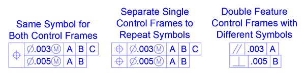
‹•› Using the QLEADER Command to Insert GD&T Feature Frame: First create the GD&T Feature Control Frame —» type QLE (QLEADER) —» Enter —» S —» in Leader Settings dialog box —» Annotation tab —» Annotation Type —» select Tolerance —» Leader Line & Arrow tab —»Leader Line —» select Straight —» Number of Points —» select 2 to select the start and enpoints of the leader line —» Arrowhead —» select None —» Angle Constraints —» First Segment —» select Horizontal or Any angle —» Second Segment —» select Horizonatal or Any angle —» OK —» Click to place the first point of Feature Frame —» Ortho mode = Off (hold down Shift) —» Click to place the second point of Feature Frame —» Fill out the GD&T Feature Frame —» Height —» leave Blank or select Projected Tolerance Zone —» OK to exit.
‹•› Using TOL Command to Insert GD&T Feature Frame without Leader: type TOL —» Enter ...or... Annotate tab —» Dimension pulldown tab —» Tolerance —» Enter the required information —» OK —» Pick a point to place the Feature Control Frame. ![]()
‹•› Using the QLEADER Command to Insert Datum-Identifying Reference Letter: type QLE (QLEADER) —» Enter —» S —» in Leader Settings dialog box —» Annotation —» Annotation Type —» select Tolerance —» Annotation Reuse —» select None/Reuse Next/Reuse Current —» Leader Line & Arrow —» Leader Line & Straight —» Number of Points —» select 2 to select the start and enpoints of the leader line —» Arrowhead —» select None —» Angle Constraints —» First Segment —» select Horizontal/Vertical —» Second Segment —» select Horizontal/Vertical —» OK —» Click to place the first point —» Ortho mode = Off (hold down Shift) to place the second point —» Datum Identifier —» type A/B or C —» OK to place.
‹•› Using the MLeader Command to Insert Datum-Identifying Reference Letter: type MLEA (MLEADER) —» Enter —» H —» click to place the leader landing location first —» click to place the landing line —» Ortho mode = Off (hold down Shift) to place the second point —» type a Datum letter —» LMBC —» select the Leader Arrowhead —» Properties —» Leaders —» Arrowhead —» select Datum Triangle Filled —» Horizontal Landing —» select No/Yes —» Text —» Attachment type —» select Vertical/Horizontal —» Text frame —» select Yes.
COMMANDS & SHORTCUTS & TIPS
Adding Fillets: Fillet —» Fillet / FIL —» type R —» Enter —» specify the radius (.xx) —» Enter —» select the first object —» select the second object —» RMC —» Repeat Fillet —» select the first object —» select the second object —» RMC to Cancel (cancel the command).
Adding Flag Notes: Create a symbol (a triangle) —» Create a text in the symbol —» Block —» Block Definition (Name + Select Objects + Pick Point) —» OK
Align Model Space and Paper Space: Autodesk have not figured out how to center paperspace or modelspace yet. —» Use the print setting to center the viewport on paper —» if anyone know how to do it like Solidwork print setting, please let us know.
Array Command: F9 (Snap Off) —» AR or Modify tab —» Array —» select objects —» Right-click —» array type: Rectangular / PAth / POlar Array —» select Grip (arrow) to edit array (click on screen to enter) —» COL —» Enter (Column spacing distance) —» R —» Enter number of Row —» Right-click —» Enter.
Center Mark: Annotate —» Dimension tab —» select Center Mark —» select a circle or an arc (continue selecting circles/arcs to place center marks —» Enter.
Change Template on Existing Drawing: Open —» Drawing —» browse and search for a template —» select a templace —» Open —» select Continue opening DWG file —» select Ignore unresolved reference files —» select Model —» select all Subject in the drawing and delete —» RMC the Title block and select Block Editor —» type ADC and enter —» search for Compane Logo —» select the logo file and RMC —» select Attach Image —» OK —» OK —» X to close window —» place the image (log) —» Close Block Editor —» Save the changes —» goto the sheet that we want to transfer the model —» in Model select all items —» Ctrl + C —» back to the template —» in Model —» Ctrl + V to paste —» close the copy drawing —» in the new drawing —» Save as to replace the copied drawing —» select Update relative paths —» edit the Title block to update drawing info.
Drawing a Circle: Circle —» Circle / C —» Enter —» (select a center point in the drawing area) —» specify the diameter —» Enter.
Drawing a Polygon: Polygon / Pol —» Enter —» (enter number of side) —» (turn on object snaps = F3) select the center of polygon —» RMC —» Enter (to accept Default = Inscribed in cirle) or select Inscribed in cirle or Circumsribed about circle —» specify radius of the circle —» Enter. The Circumscribed option draws a polygon whose sides are tangent to the circumference (đường tròn, chu vi) of the circle.
Drawing a Rectangular: Draw —» Rectangle / RECT —» F12 Tooltip On/Off (click in the drawing area) —» type X dim, Y dim (Dynamic Input button is on for this step. If it’s not, AutoCAD treats an input of 36,36 as absolute coordinates) —» Enter.
NỘI DUNG TÀI TRỢ

Quảng Cáo Dịch Vụ

Quảng Cáo Sự Kiện

Quảng Cáo Khuyến Mãi

Biểu Trưng & Nhãn hiệu
Hỗ trợ chúng tôi và phát triển doanh nghiệp của bạn với chúng tôi. Mục tiêu của tôi là cung cấp thông tin kỹ thuật với khả năng truy cập sẵn sàng vào các tài nguyên, công thức và tài liệu tham khảo thường cần thiết trong khi thực hiện công việc của mình với tư cách là Kỹ sư hỗ trợ kỹ thuật. Các doanh nghiệp được liệt kê trong Nội dung được Tài trợ đã được lựa chọn cẩn thận vì tính độc đáo của chúng. Tuy nhiên, các quảng cáo liệt kê không được tài trợ sẽ được luân chuyển thay đổi hàng tháng.
ViBa Direct thiếu một ban cố vấn để thực hiện nghiên cứu và thuê các nhà văn với kiến thức kỹ thuật hiện đại. Việc tạo ra một ban cố vấn hiệu quả đòi hỏi nhiều hơn là một lời mời. Nếu không có sự tài trợ của bạn, điều này khó có thể thực hiện. Nếu công ty của bạn có nhu cầu quảng cáo, đặt biểu trưng, thương hiệu, biểu ngữ mời tham gia thảnh viên, hội viên cũng như các bích chương quảng cáo ở đây hoặc trên bất kỳ trang nào khác, xin vui lòng liên hệ Dịch Vụ Khách Hàng Dịch Vụ Khách Hàng để biết thêm chi tiết.
Dynamic Input Tooltip —» F12 Tooltip On/Off — DSETTINGS —» Dynamic Input —» check Enable Pointer Input (select Settings for options) + Enable Dimension Input where possible (select Show 2 dimension input fields at a time) + Show command prompting and command input near the crosshairs + Show additional tips with command prompting (select Drafting Tooltip Appearance for options) —» OK.
Fill: AT (hatch) —» S (selet object) —» Hatch Creation panel —» select pattern (ex: solid, angle, ansi) —» Close Hatch Creation —» select the created hatch —» RMC —» Property —» change the object properties here (color, scale, linetype, etc).
Fillet a Rectangular: Fillet —» Fillet / FIL —» type R —» specify the radius (.xx) —» Enter —» select Polyline / P —» select the rectangle —» RMC to Cancel or Esc.
Hatch: Turn off Snap / F9 —» Ortho / F8 —» Object Snap / F3 —» Create a Hatch Layer and Set current—» H or Draw tab —» Hatch —» Select objects —» Properties —» select ANSI31 —» Scale = 1.0 (or type in a number to change) —» Angle (type in a number to change) —» Right-click —» Enter.
Image in DWG: insert a raster image into a DWG file so that there is no need for an external image file. Example, like the company logo to be part of the title block. Open the raster image in an image editing application, such as Microsoft® Paint —» select All (Ctrl+A) —» Copy (Ctrl+C) —» in AutoCad Paste (Ctrl+V) —» place the logo and size to fit.
Modify Dimension Style: Lines, Symbols and Arrows, Text, Fit, Primary Units, Alternate Units, Tolerances —» Dimsty or select a Feature + Enter.
Multiple Text Object: Creates a multiline text object with a field that can be updated automatically as the field value changes. Fields can be inserted in any kind of text except tolerances. The FIELDEVAL system variable and the UPDATEFIELD command determine how fields are updated. Fields can be inserted in any kind of text (except tolerances), including text in table cells, attributes, and attribute definitions. When any text command is active, Insert Field is available on the shortcut menu. Some sheet set fields can be inserted as placeholders. Ex: Insert SheetNumberAndTitle as a placeholder. Later, when the layout is added to a sheet set, the placeholder field displays the correct sheet number and title. Block placeholder fields can be used in block attribute definitions while you're working in the Block Editor. —» Type FIELD + Enter.
Navigation Bar —» NAVBAR (On/Off) — System Variable —» NAVBARDISPLAY (On/Off).
Offset an Object: Modify —» Offset / O —» specify offset distance —» Enter —» select the original object —» click where to offset —» RMC to Cancel.
Printing / Ploting: Paper space layouts is for creating arrangements of the drawing to be plot, these arrangements usually include a title block. PLO / Ctrl + P or Print Icon —» Printer/ploter (select a printer) —» Paper size (select the paper size) —» Plot area (select Limits: This is the entire drawing area specified with the drawing set up) —» Plot offset (select the Center the Plot check box) —» Plot scale (deselect the Fit to Paper check box and choose 1:10 – Scale used to setup the drawing) —» Plot Style Table (choose monochrome.ctb) —» Yes —» drawing orientation (Lanscape / Portrait) —» Preview —» x (close) —» OK (to print).
Project Manager Panel: To open the Project Manager Panel —» start AutoCAD Electrical —» + (new drawing) —» select Project tab —» in Project Tool Panel select Manager. A project is a set of interrelated electrical drawings. A project file lists the AutoCAD drawing file names that make up the drawing set. Many projects can be creates as you wish, but only one project is active at a time.
Setting up Layers: Layer Properties —» LA —» New Layer —» Name = Column —» color = 5 (blue) —» New Layer —» Name = Part Feature (ex: Base, Holes) —» color = 4 (cyan) —» New Layer —» Name = Dim —» color = 7 (black) —» select Part —» RMC —» set Current —» OK
Stretch Command: To stretch or move objects. The key to using STRETCH is specifying a crossing selection box properly. S or Modify tab —» Enter —» select objects (by crossing-window or crossing polygon) —» Right-click —» select a base point —» F8 / Ortho On —» enter the distance to stretch —» Enter.
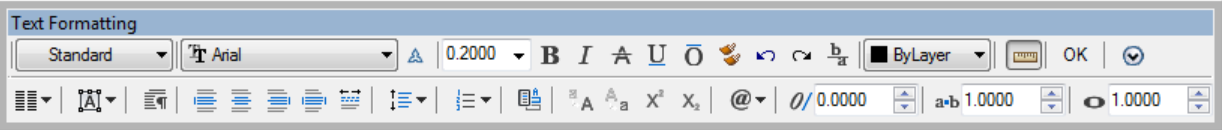
Text Formatting Toolbar: Type PICKFIRST —» pick 1 to turn it on —» type DBLCLKEDIT and change the value to ON.
Text Style: A text style is a collection of text settings that controls the appearance of text, such as font, line spacing, justification, and color. Type STYLE —» to create text styles to specify the format of text quickly.
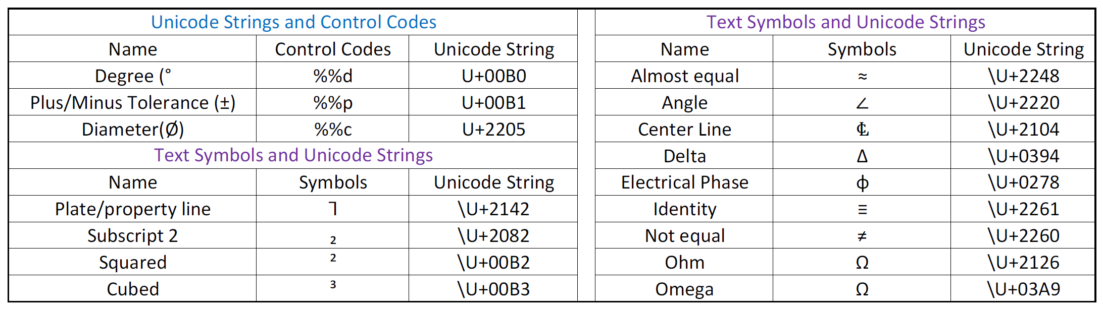
TEXT, SYMBOLS & SPECIAL CHARACTERS
Symbols can be inserted in text using one of the following methods:
‹•› In the In-Place Text Editor, right-click and click Symbol.
‹•› On the expanded Text Formatting toolbar, click Symbol.
‹•› Copy and paste from the Character Map.
‹•› Enter the control code or Unicode string. Note: Precede the Unicode string with a backslash ( \ ). See examples below.
Your Support Can Help Us Grow. Thank you for visiting ViBa Direct. As part of our commitment to continually improving the visitor experience, we’re doing our best to add the latest information with ready access to commonly needed resources, engineering, formulas, reference materials, photography, and travel. Unfortunately, we don't have enough manpower to meet everyone's needs. But if you are interested in helping us with the site maintenance cost. Please mail your donation to ViBa Direct., P.O. Box 1801., Pflugerville, TX 78691. Thank you for taking the time to read this. Feel free to Customer Service with any additional feedback you would like to share about your experience visiting ViBaDirect.com


