|
|
DATUM, DATUM FEATURE, DATUM TARGET – ASME Y14.5-2009
A datum is a theoretical (lý thuyết, giả định) exact point, axis, or plane derived (bắt nguồn từ) from the true geometric counterpart (bộ phận tương ứng) of a specified datum feature. A datum (điểm tính) is the origin from which the location (địa điểm hoặc vị trí) or geometric characteristics (nét đặc trưng; đặc điểm) of features of a part are established (lập, thành lập, thiết lập). Datums (Điểm cố định) are theoretically perfect but imaginary planes, axises, and points used for creating reference frame in a drawing. This reference frame is used for dimensioning for the drawing and model creation. 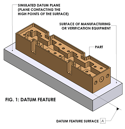 Datums are established from the datum features. If we have a point datum, then only one datum is sufficient to constrain the model. In the case of planes, we need three mutually perpendicular ones. If we have axis and plane, then one axis and one plane will suffice for the need.
In Fig.1d example, if a slot is located from a surface with a coordinate dimension and tolerance, no point on the slot center plane may be any closer to or farther away from any point on the surface than the specified limits. All high and low points on the surface must be taken into account even in cases where the low points have no bearing on the functional acceptability of the part. A measurement of less than 24.50 mm would cause the part to be rejected even though it may be functionally acceptable. The use of datum and an appropriate geometric tolerance would provide a means of defining a functiona relationship between the slot and bottom of the part.
Datum Feature: A datum feature is an actual feature of a part that is used to establish a datum. A hole is an example of something that can be used as a datum feature because it's a feature that can be seen or touched. Cneterlines, center planes, and theoretical axes are not identified as datum features because they do not physically exist.
Datum Dimensioning (Implied datum): All dimensions orginate from a common surface (also common axis or center plane the datum are assumed (implied; ám chỉ, ngụ ý, bao hàm).
‹•› Do not clearly specify which surfaces are to contact the inspection equipment.
‹•› Do not communicate to the drawing user in which sequence the part should be brought into contact with the inspection equipment.
Datum Feature Selection: The most important quality you want in a datum feature is leadership (cương vị lãnh đạo). A good datum feature (actual feature on a part) is a surface that most strongly influences (ảnh hưởng, tác dụng) the orientation (sự định hướng) and/or location of the part in its assembly. 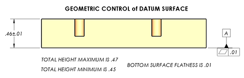 We call that a "functional (thiết thực; thực dụng)" datum feature. A good datum feature should be able to take on the weight of the part and provide stability and avoid "downcast" (không chính sát) and "unfinished" (chưa hoàn thành) surfaces with high and low spots. Choose a datum feature that's likewise always accessible for fixturing during manufacturing, or for inspection probing (khảo sát) at various stages of completion. Datum features are selected based on their importance to the function of the part and assembly requirements. They are often the features that orient (stablize) and locate the part in its assembly.
Datum Feature Simulator (vật/người tái tạo "một số điều kiện" bằng một mô hình "để nghiên cứu, để huấn luyện.."): If quality is not assured by the initial design, then expensive change orders will have to be carried out, wasting valuable engineering resources and possibly including further quality problems in the process. Optimize (hoàn chỉnh; đúng, chính xác, or functional as possible) tolerances for a robust design using GD&T to ensure the high quality by design.
‹•› Opposite shape of datum feature.  Do not use letter I, O, or Q. Use double letters when number of datum exceeds number of letters in alphabet.
‹•› Two types: Theoretical (lý thuyết, không thực tế) datum feature simulator (tái tạo "một số điều kiện" bằng một mô hình "để nghiên cứu, để huấn luyện..") and Physical datum feature simulator.
‹•› Manufacturing examples: Machine tables, surface plates, gauge surfaces, surface tables, specially designed rotation devices.
Datum Feature Symbol: Do not apply to centerlines, center planes, or axes. Draw using thin lines.
Datum Feature Symbol Placement for Planar (mặt phẳng) Datums: On drawing view where the surface appears as an edge. On the extension line projecting from the edge view of a surface (should be offset from arrowhead). Attached to a feature control frame (associated with a feature). On a chain line when specifying a partial datum surface. The datum features are used to restrict the transitional and rotational movement of the part when it placed in fixtures.
Datum Feature Terms: Actual mating envelope - Simulated datum - Tangent (tỉ số giữa cạnh đối và cạnh kề của một góc đã cho trong một hình tam giác vuông) plane.
Datum Surface: Flat surfaces are commonly used as datum features. Can be controlled by geometric tolerance - Datum plane measurements do not take variations in datum surface from datum plane into account.
DATUM REFERENCE FRAME
Datum Reference Frame (DRF) Concept:A DRF is made up of three multually perpendicular planes. These planes locate the three axes that form an X, Y, and Z coordinate system. Select three perpendicular datum features based on their importance to part design. Assign precedence (thứ bậc, quyền ưu tiên) and datum reference order. The X, Y, and Z axes may be identified on the drawing, and identifying them is required if the datum feature references include degrees of freedom notations called a customized datum reference frame.
Planes in a datum reference frame are always mutually perpendicular and perfect. Although a perfect datum preference frame is located by imperfect datum features, the imperfections in the features are not permitted to affect the datum reference frame. The planes of the datum reference frame remain mutually (hỗ trợ, hỗ tương) perpendicular regardless of the conditions of the datum features. This is important, because it prevents the variation in the datum features from affecting the measurement of the toleranced features.
‹•› Primary datum: At least three points (known as high points) anywhere on the primary datum feature in contact with the first datum plane.
‹•› Secondary datum: At least two points anywhere on the secondary datum feature in contact with the second datum plane (restricts part movement).
‹•› Tertiary datum: At least one points anywhere on the tertiary datum feature in contact with the third datum plane (restricts part movement).
Datum Reference Frame Concept: Inspecting the part.
‹•› All parts have six degrees of freedom: Three degrees of translation. Three degrees of rotation.
‹•› Movement is either translational or rotational.
Establishing Multiple Datum Reference Frames: Datum X, Y, and Z establish one datum reference frame. Datums L and M establish second datum reference frame.
Datum Features Specified Individually: Place a note next to datum features symbols indicating how many datum features to consider separately. Place the note "2X INDIVIDUALLY" next to datum feature symbols of two separate datum features identified by same letter.
DATUM TARGETS
Datum Target: Datum targets are specified regions of the datum feature used for locating the part in a fixture. Datum targets are generated from the datum features. The sole purpose of the datum target is for locating or constraining the part to a fixture. But, for specifying the datum targets we use some portions of the datum features. As per the 3-2-1 principle, we typically define three primary datum targets, two secondary datum targets, and one tertiary datum targets.  In the below example, the primary datum targets “X1", “X2" and “X3" are circular surfaces of diameter (.25"), the secondary datum targets “Y1" and “Y2" are the surfaces of diameter (.50") and the tertiary datum targets “Z1" is of diameter (.375").
‹•› Points, lines or surface areas of contact on a part used to establish the datum planes or axes (when it is not possible to use a surface); describe the size, shape, and location of gage elements.
‹•› Used when it is not practical (thực tế, trên thực tế, thực sự) to use the entire surface as a datum plane, the designer suspects the part may rock or wobble (sực lắc lư, sự lung lay) when the datum feature contacts the datum plane, and only a portion of the feature is used in the function of the part.
Datum Target Symbol: Identify datum targets. Useful on parts with surface or contour (đường viền, đường quanh) irregularities (tính không theo quy tắc). Connect to datum target point, line, or area with a leader.
Bottom half denotes (có nghĩa là) the datum letter and target number. Top half contains the diameter (or gage element size) when applicable.
‹•› Dashed (hidden) line used when the target is on the hidden surface side of the part (the surface you cannot see behind the plan view surface)
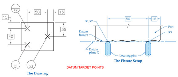
Datum Target Points: Datum plane established by locating pins at datum target points.
‹•› Establish primary datum plane by locating at least three points on primary datum surface.
‹•› Establish secondary plane by locating at least two points on related secondary datum surface.
‹•› Establish tertiary datum plane by locating at least one point on related tertiary datum surface.
‹•› Datum target points (specified with an X-shaped symbol) are shown and dimensioned on the plan view of the surface to which it is being applied — the datum feature symbol is still shown in its proper location (if the surface view is not available, the symbol can be shown on two adjacent views).
‹•› Dimension using baseline or chain dimensioning. Location dimensions originate from datums.
‹•› Used to establish datums using areas of contact. Indicated by the shape of the area outlined w/phantom lines with section lines through the area. 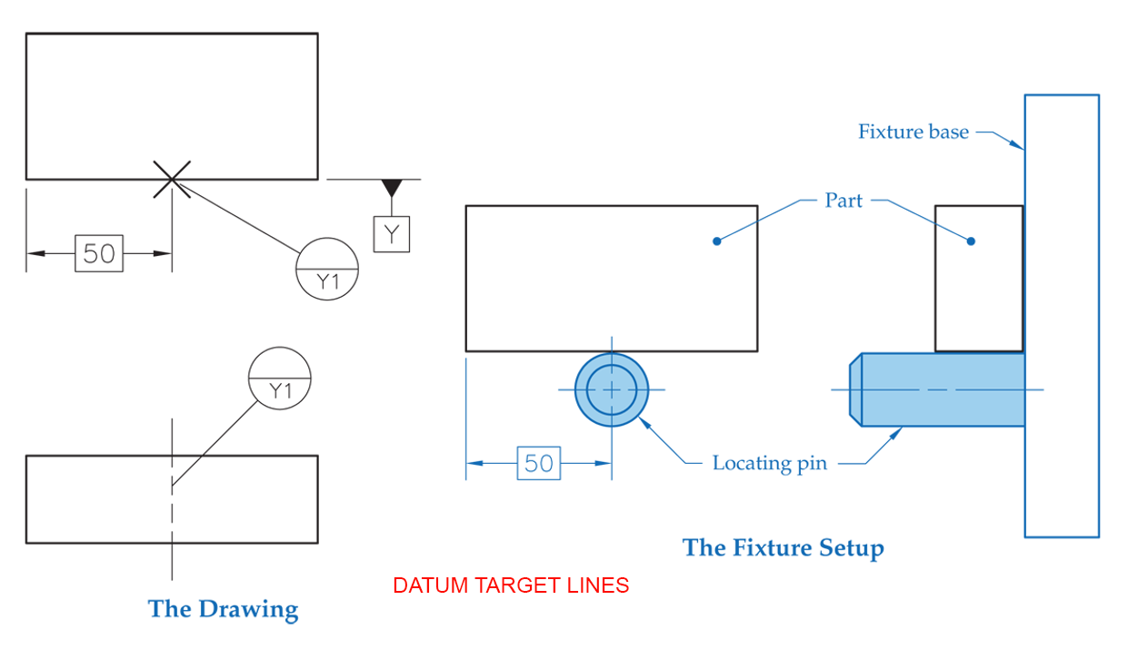
‹•› Locating pins are flat end tooling pins with pin diameter equal to specified size of target area.
‹•› Top half of the datum target symbol identifies size of target area.
‹•› Use datum target point at center location when area is too small to accurately or clearly display on drawing.
Datum Target Lines: Line of contact used to establish datum.
‹•› Indicated by a target point on edge view of surface and a phantom line on surface view.
‹•› Locating pins are cylindrical or knife-edged with datum target line along tangency where pins meet the part.
‹•› Surface is often placed 90° to the pin to create datum reference frame.
Inclined (dốc nghiêng, có khuynh hướng, có chiều hướng) Datum Features: When a datum is at an angle other than 90°, the part feature (surface) must be dimensioned with a basic dimension and must be controlled by a geometric tolerance. 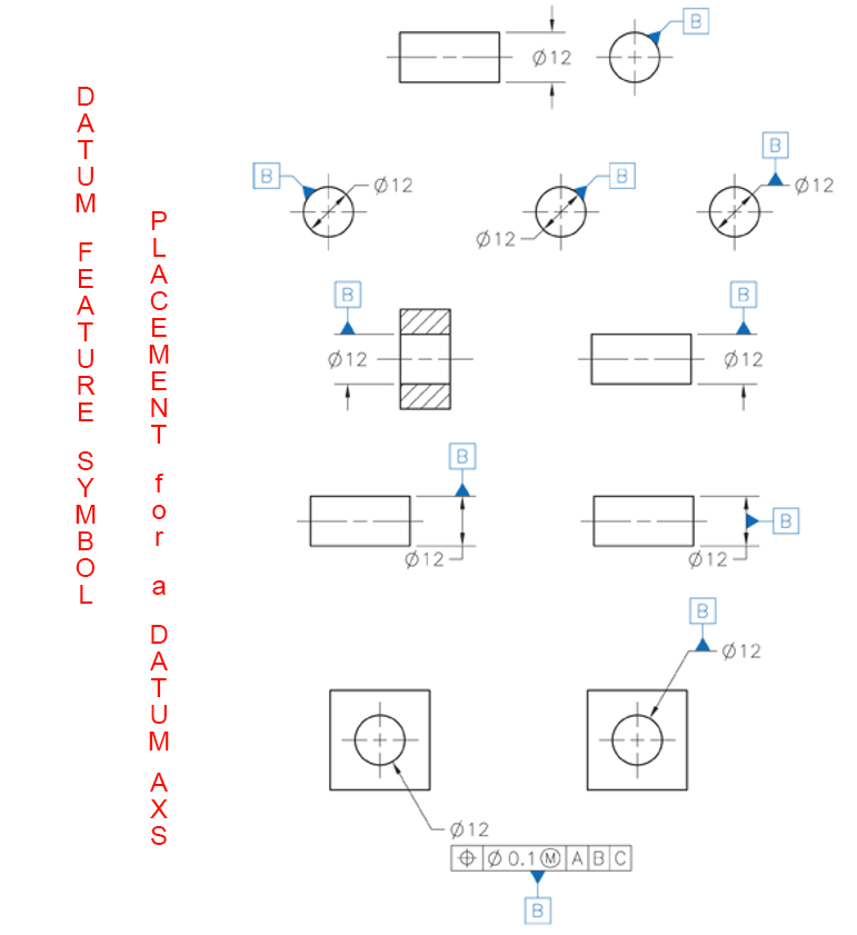
Partial (một phần; không hoàn chỉnh) Datum Surface: Portion of a surface used as a datum. Drawn as a chain line dimensioned with basic dimensions to show the location extent of the partial datum surface..
Coplanar (đồng phẳng) Surface Datums: Two or more surfaces that are on the same plane. Drawn with phantom line between the surfaces if a void (chỗ trống, khoảng không trống rỗng) is exits. Both datum letters are placed in the feature control frame and are separated by a dash.
Datum Axis: Represents two theoretical planes intersecting at 90°. Represented in drawings with centerlines.
‹•› Pitch cylinder for screw threads establishes datum axis unless otherwise specified.
‹•› When not using pitch cylinder for screw threads, place note such as "MAJOR DIA" or "MINOR DIA" next to datum feature symbol.
‹•› Simulated datum axis establised by inspection equipment.
Datum Axis in Parallelism: Lines or surfaces may be required to be partallel with datum planes or axis. Tolerance zones may be the space between two parallel lines or surfaces or the space contained within a cylinder positioned parallel to its datum. The magnitude of the tolrence value is the distance between the parallel lines or surfaces or the cylinder diameter. 
Coaxial (đồng trục) Datum Features: Separate datum reference letters by a dash in one compartment of the feature control frame.
Datum Axis Established with Datum Target Symbols:
‹•› Primary datum axis established by two sets of three equally spaced targets. Identify datum target points in correlation (sự tương quan) to adjacent (góc kề,gần kề) cylindrical datum feature when two cylindrical features of different diameters establish a datum axis.
‹•› Identify datum target points in correlation to adjacent cylindrical datum feature when two cylindrical features of different diameters establish a datum axis.
‹•› Cylindrical datum target areas and circular datum target lines can be used to establish datum axis.
‹•› Target area represented by two phantom lines with section lines between.
‹•› Datum target line represented by phantom line all around part.
‹•› Establish secondary datum axis by placing three equally spaced targets on cylindrical surface.
Movable Datum Target Symbols and Datum Target Points: When datum targets establish a center point, axis, or center plane on a RMB (Regardless of Material Boundary — This is the condition whare stated tolerance limits must be met irrespectively of as built datum feature size or location.) basis, datum feature simulator movement is normal to true profile.
Movable Datum Target Symbols and Datum Target Spheres: Circular phantom line represents spherical (hình cầu) datum feature simulator to establish datum axis.
DATUM CENTER PLANE & TRANSLATION MODIFIER
Datum Center Plane: Axis and center plane datum feature symbols align with/replace dimension line arrowhead or appear on feature, leader shoulder, dimension line, or feature control frame.
Translation Modifier (từ bổ nghĩa): Added to feature control frame following datum feature reference and any other applicable modifiers. Specifies that basic location of datum feature simulator is unlocked and free to translate within specified geometric tolerance.
Using Contoured Surface as Datum Feature: 3D mathematical coordinate system defines compound (hợp chất, pha trộn, đa hợp, hợp) surface feature on a part. Datum simulator results from mathematical data. Common when design copies contour of an actual object that has few or no flat surfaces to use as datums.
DEGREES OF FREEDOM; DATUM & DATUM FEATURE
Compound Datum Features are two or more used at the same time to establish one datum. Rotating shafts are commonly supported by two or more bearings. Multiple bearing surfaces are functional in these situations and should be used to establish the axis of rotation for the shaft. Specifying compound datum features permits the design tolerances to reflect the functional needs of a rotating shaft. The standard method refers to the use of more than one datum feature to create a single datum as compound (multiple) datum features.
Degrees of Freedom: (page 5-72).
Six Degrees of Freedom: 6DoF refers to the freedom of movement of a rigid body in three-dimensional space. Specifically, the body is free to move forward/backward, up/down, left/right (translation in three perpendicular axes) combined with rotation about three perpendicular axes, often termed pitch, yaw, and roll.
Datum: A datum is a theoretically exact point, axis, line, plane, or combination thereof derived from the theoretical datum feature simulator (used as a reference for tabular dimensioning). A datum is the origin from which the location or geometric characteristics of features of a part are established.
‹•› Tabular Dimensioning: A form of arrowless dimensioning in which dimensions to features are shown on a table.
‹•› Chart Dimensioning: A unidirectional, aligned, arrowless, or tabular dimensioned drawing used when dimensions change values.
Implied Datum: An assumed plane, axis, or point drom which a dimensional measurement is made.
Datum Feature: A datum feature is a feature that is identified with either a datum feature symbol or a datum target symbol (page 5-61).
Datum Feature Selection: (page 5-61).
Datum Feature Simulator (Theoretical): A datum feature simulator (Theoretical) is the theoretically perfect boundary used to establish a datum from a specified datum feature.
Datum Feature Simulator (Physical): A datum feature simulator (Physical) is the physical boundary used to establish a simulated datum from a specified datum feature. Physical datum feature simulators are represented by inspection or manufacturing tooling
Datum Reference Frame: A datum reference frame consists of three mutually perpendicular intersecting datum planes.
True Geometric Counterpart or TGC: (page 5-67).....developing subjects.


