|
|
TOLERANCES OF LOCATION — TOLERANCE OF POSITION
Position is a versatile (nhiều tác dụng; đa năng) tolerance that can be used to control location, coaxiality, orientation or axis offset of a part feature or axis. Position should be specified whenever the design requirements permit. This control provides an opportunity to utilize (dùng, sử dụng; tận dụng) many of the advantages of GD&T.
Position (xác định vị trí) is the perfect location of a feature of size in relation to a datum or datums. This is the first rule. 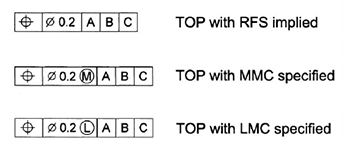 Surfaces cannot be controlled with a position tolerance (surface can be controlled with a profile of a surface tolerance). Only feature of size can have a position tolerance applied to them. See Figure on the right.
How Does It Work? A positional tolerance defines either of the following:
1. A zone within which the center, axis, or center plane of a feature of size is permitted to vary from a true (theoretically exact) position.
2. A position tolerance may be specified in an RFS, MMC, or LMC context.
‹•› When specified on an Regardless Feature of Size (RFS) basis, a TOP (tolerance of position) control defines a tolerance zone that the center, axis, or center-plane of the "Actual Mating Envelope (AME)" of a POS must be within.
‹•› When specified on an MMC or LMC basis, a TOP control defines a boundary – often referred to as the virtual condition – that may not be violated by the surface or surfaces of the considered feature.
3. Where specified on an MMC or LMC basic. A boundary, defined as the virtual condition, located at the true theoretically exact position, that may not be violated by the surface or surfaces of the considered feature of size.
How to Apply It? A positional tolerance (kích cỡ, khối lượng, của một bộ phận có thể dao động mà không gây tác hại) is specified using a feature control frame displaying the "position" characteristic symbol followed by a compartment containing the positional tolerance value. Within the compartment, the positional tolerance value may be followed by an MMC or LMC modifying symbol. Any additional modifiers, such as "statistical tolerance," and/or "projected tolerance zone" followed by one, two or three separate compartments, each contaning a datum reference letter. Each datum reference may be followed by an MMC or LMC modifying symbol, as appropriate to the type of datum feature and the design.
True Position is the theoretically exact location of a Feature of Size (FOS) defined by basic dimensions. Expressed as the total permissible variation that a feature can have from its “true” position. Depending on how it is called out, true position can mean several different things. It can be used with MMC (Max Material Condition), LMC (Least Material Condition), projected tolerances (P), and tangent planes (T).
Dimensions for True Position: For each individual controlled feature, a unique true position shall be established with basic dimensions relative to a specified DRF (Datum Reference Frame). True position is the nominal or idal orientation and location of the feature and thus, the center of the virtual condition boundary or positional tolerance zone. The basic dimensions may be shown graphically on the drawing, or expressed in table form either on the drawing or in a document referenced by the drawing.
‹•› Base line dimensioning: For each of the two Ø.376 holes, a basic dimension originates from each plane of the DRF. Manufacturers prefer this method because it directly provides them the coordinates for each true position relative to the datum origin. CMM inspection is simplified, using a single 0,0 origin for both holes.
‹•› Chain dimensioning: A basic dimension of 1.500 locates the upper Ø.500 hole directly from the center plane. 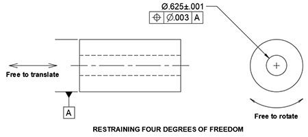 However, the lower Ø.500 hole is located with a 2.500 basic dimension from the true position of the upper hole. We often confuse the 2.500 basic as originating from the actual axis of the upper hole, rather than from its true position. A manufacturer needing the coordinate of the lower hole will have to calculate it 1.500 – 2.500 = – 1.000.
‹•› Implied symmetry dimensioning: In many cases, the applicable basic dimensions are iplied by drawing views. The true positions of the two Ø.750 holes have a single 3.000 basic dimension between them, but no dimension that relates either hole to the planes of the DRF. Since the holes appear symmetrical about the center plane of the DRF, that symmetrical basic relationship is implied (ngụ ý, bao hàm, ám chỉ).
‹•› Implied zero-basic dimensions: The view implies the relationship of the Ø.750 hole to the planes of the DRF as represented by the view's center lines. Obviously, the hole's basic orientation is 0° and its basic offset from center is 0. These implied zero-basic values need not be explicated (giải nghĩa, giải thích).
‹•› Implied basic 90° angles: A 90° basic angle applies where centerlines of features in a pattern (or surfaces shown at right angles on a drawing) are located and defined by basic dimensions and no angle is specified.
Polar coordinate dimensioning: Rather than by rectangular coordinates corresponding (tương đương hoặc tương tự) to two perpendicular axes of the DRF, the true position of the eight Ø.750 holes are defined by polar coordinates for angle and diameter. The Ø6.000 "bolt circle" is basically centered at the intersection of the datum planes, and the two 45° 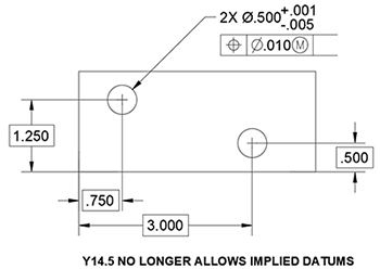 basic angles originates from a plane of the DRF. Figures. b and c show alternative apporaches that yield equivalent results, based on various methods and fundamental rules. All presented methods are acceptable. Designer can choose between base line and chain dimensioning. While both methods yield identical results, base line dimensioning is prefered even if the designer has to make some computations to express all the dimensions originating from the datum origin. Doing so once will preclude (ngăn ngừa, làm cho không thể xảy ra) countless error-prone calculations down the road.
Datums for Positional Control: Every positional tolerance shall reference one, two or three datum features. The DRF need not restrain all six degrees of freedom, only those necessary to establish a unique orientation and location for true position. Ex: The DRF established in the right Fig. restrains only four degrees of freedom. The remaining two degrees, rotation about and transtaltion along the datum axis, have no bearing on the controlled feature's true position. Thus, further datum references are meaningless and confusing.
For many positional tolerances, such as those in the right Figure, the drawing view makes it quite obvious which part features are th origins, even if they weren't identified as datum features and referenced in the feature control frame. Although we may agree the part's left and lower edges are clearly datum features, we might disagree on their precedence in establishing the orientation of the DRF.  In another example, where a part has multiple coaxial diameters, it might be obvious to the designer, but very unclear to the reader, which diameter is supposed to be the datum feature. For these reason, Y14.5 no longer allowed implied datums.
Position tolerance is a geometric dimensioning and tolerancing (GD&T) location control used on engineering drawings to specify desired location, as well as allowed deviation to the position of a feature on a part.
‹•› A position tolerance defines the allowable deviation from true position.
‹•› The tolerance for a true position or basic dimension must come from a geometric tolerance.
‹•› When using a position tolerance, the true position of the feature of size must be defined.
Position Tolerance Requirements:
1. Must be applied to a feature of size or a pattern of features of size. 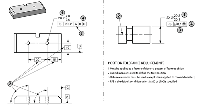
2. Basic dimensions used to define the true position.
3. Datum references must be used (except when applied to coaxial diameters).
4. RFS is the default condition unless MMC or LMC is specified.
The two common zone shapes for a position tolerance.
Modifiers that can be used with a position tolerance, and when each material condition modifier (MMC, LMC, or RFS) should be used in a position tolerance. The M modifier lowers production cost. The P modifier is used for alignment.
Two tolerance zone interpretations for position tolerances. Position RFS axis and position MMC surface.
‹•› When should the surface interpretation be used for a geometric tolerance? When the MMC modifier is specified in the feature control frame. Surface interpretation for position tolerance on a pattern of holes. Surface interpretation for position tolerance on a width.
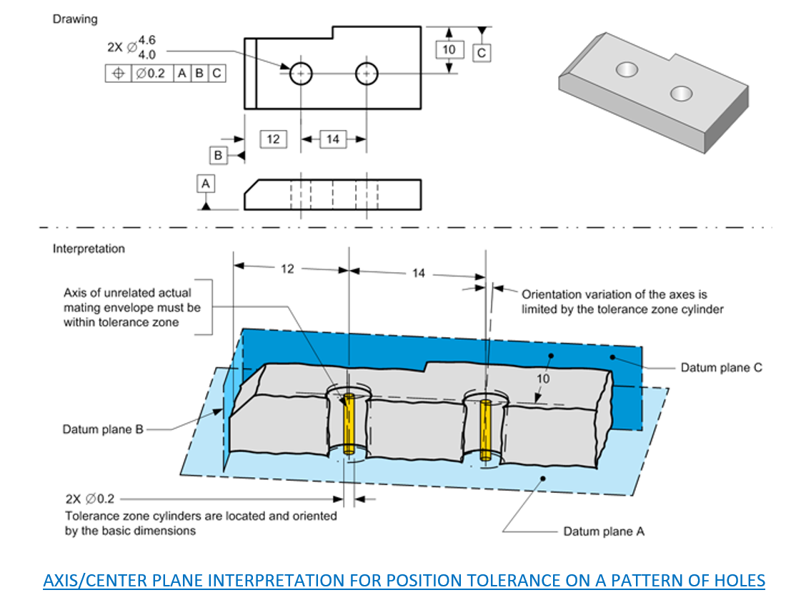 Axis/Center Plane Intepretation for Position Tolerance on A Pattern of Holes: Axis of unrelated actual mating envelope must be within tolerance zone. Tolerance zone cylinders are located and oriented by the basic dimensions. Orientation variation of the axes is limited by the tolerance zone cylinder. Pattern of Holes Controlled with TOP Using RFS. Coaxial (đồng trục) Diameters Controlled with TOP Using RFS.
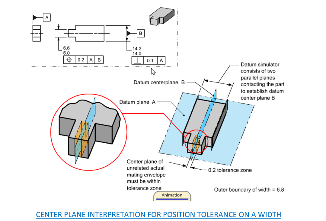
Center Plane Interpretation for Position Tolerance on A Width: Center plane of unrelated actual mating envelope must be within tolerance zone. Datum simulator consists of two parallel planes contacting the part to establish datum center plane.
Position Tolerance and Conditions That Applied at RFS:
‹•› Where a position tolerance is applied at RFS, a bonus tolerance is not permitted.
‹•› Where a position tolerance is applied at RFS, the axis/center plane interpretation is used.
‹•› Where a position tolerance is applied at RFS, the tolerance zone is located by basic dimensions. 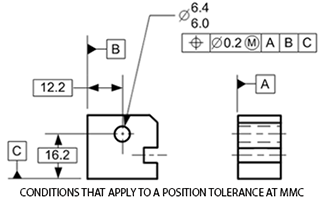
Position Tolerance and Conditions That Applied at MMC:
‹•› Where a position tolerance is applied at MMC, a bonus tolerance is permitted.
‹•› Where a position tolerance is applied at MMC, the axis/center plane interpretation is not used.
‹•› Where a position tolerance is applied at MMC, the tolerance zone is located by basic dimensions.
Positional Tolerance and Angled Features: Positional tolerancing is especially suited to angled feature over it entire length. This presumes (cho là, coi như là) the feature has no functional interface (mặt phân giới) beyond its own length and breadth (bề ngang, bề rộng, khổ). However, in the right figure, a pin is pressed into the controlled hole and expected to mate with another hole in a cover plate. The mating feature is not the pin hole itself, but rather the pin, which represents a projection of the hole. Likewise, the mating interface is not within the length of the pin hole, but above the hole, within the thickness of the cover plate. 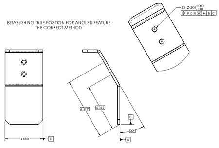 See Figure. Establishing true positions from an implied datum – a common error.
If the pin hole were perfectly perpendicular to the plannar interface between the two parts, there would be no difference between the location of the hole and the pin. Any angulation (hình có góc), however, introduces a discrepancy (sự khác nhau) in location. This discrepancy is proportional (tương ứng về cỡ, số lượng hoặc mức độ ; có tỷ lệ đúng; cân xứng) to the length of projection. Thus (do đó, theo đó, vì thế, vì vậy), directly controlling the location of the pin hole itself is inadequate (không tương xứng, không xứng, không thích đáng, không thoả đáng) to assure assemblability. Therefore (bởi vậy, cho nên, vì thế, vậy thì), the location of the hole's projection (hình chiếu) needed to be control, which could be thought of as a phantom pin. this is accomplished with a positional tolerance modified with a projected tolerance zone.
Positional Tolerance and Projected Tolerance zone. The application of this concept is recommended where the variation in perpendicularity of threaded or press-fit holes could cause fastener, such as screws, studs, or pins, to interfere with mating parts. In figure 1.a, an interference can occur where a tolerance is specified for the location of a threaded or press-fit hole, and the hole is inclined within the positional limits. Unlike the floating fastener application involving clearance holes only, the attitude of a fixed fastener is governed by the inclination of the produced hole into which it assembles. Figure 1.b illustrates how the projected tolerance zone concept realistically treats the condition show in previous figure 1.a. Note that it is the variation in perpendicularity of the portion of the fastener passing through the mating part that is significant. The location and perpendicularity of the threaded hole are only of important in so far as they affect the extended portion of the engaging fastener. When design considerations require a closer control in the perpendicularity of a threaded hole than that allowed by the positional tolerance, an orientation tolerance applied as a projected tolerance zone may be specified. 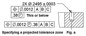
A projected tolerance zone is defined to predict the final dimensions and locations of features on a component or assembly subject to tolerance stack-up. A projected tolerance zone exits outside the extent of the tolerance feature of size. A projected tolerance zone is specified by placing the symbol P with a circle after the tolerance value in the position feature control frame. This establishes a constant-size (kích thước, cỡ, khổ không thay đổi) central tolerance zone bounded either by two parallel planes separated by a distance equal to the specified tolerance, or by a cylinder having a diameter equal to the specified tolerance. For blind holes and other applications where the direction of projection is obvious, the length of projection may be specified after the symbol in the feature control frame. This means the projected tolerance zone terminates at the part face and at the specified distance from the part face (away from the part, and parallel to the true position axis or center plane). The projection length should equal the maximum extension of the mating interface. In Figure. a (pin and cover plate example). the projection length must equal the cover plate's maximum thickness .38. 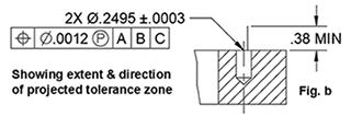 Where necessary, the extent and direction of the projected tolerance zone are shown in a drawing view as a dimensioned value with a heavy chain line drawn next to the center line of the feature as in Figure. b.
‹•› At RFS: The extended axis or center plane of the feature's actual mating envelope (as defined in Derived Elements) shall be contained within the projected tolerance zone.
‹•› At MMC: The extended axis or center plane of the feature's applicable Level 2 MMC perfect form boundary (as defined in Level 2 – Overall Feature Form) shall be contained within the projected tolerance zone. This example explain as the feature's size departs from MMC, the feature fits its MMC perfect form boundary more loosely. This permits greater deviation in the feature's orientation and/or location. A hole's departure from MMC permits assembly with a mating pin having its axis anywhere within a conical (hình nón) zone. The alternative center method described in (Level 2 – Overall Feature Form) cannot be used for a projected tolerance zone. Its bonus tolerance would simply enlarge the projected tolerance zone uniformly along its projected length, failing to emulate the feature's true functional potential.
‹•› At LMC: (page 5-120).....developing subject.
Verify a position tolerance with the projected tolerance zone modifier: One common method for verifying a projected tolerance zone is to use gage pin inserted into the tolerance feature of size with an extension protruding up for the height of the projected tolerance zone. The height of a projected tolerance zone is often determined by the maximum height of the hole in the mating part.
Positional Tolerance at MMC: A positional tolerance applied at MMC may be explained in terms of the surface or the axis of the feature of size. In certain cases of extreme form deviation (within limits of size) or orientation deviation of the hole, the tolerance in terms of the axis may not be exactly equivalent to the tolerance in terms of the surface. See Im_1-13. In such cases, the surface interpretation shall take precedence. In some instances, the additional tolerance may indirectly benefit features other than the one that departed from MMC.
‹•› Surface Interpretation: While maintaining the specified size limits of the feature, no element of the surface shall violate a theoretical boundary (virtual condition) located at true position. See Im_1-14.
- When should the surface interpretation be used for geometric tolerance? When the MMC modifier is specified in the feature control frame, see (Surface Interpretation for Position on a Pattern of Holes — Surface Interpretation for Position Tolerance on a Width — Axis/Center Plane Interpretation for Position Tolerance on A Pattern of Holes — Center Plane Interpretation for Position Tolerance on A Width).
‹•› Axis or Center Plane Interpretation: Where a feature of size is at MMC, its axis or center plane must fall within a tolerance zone located at true position. The size of this zone is equal to the positional tolerance. See Im_1-15, (note/illustrations no, 1 and 2). This tolerance zone also defines the limits of variation in the orientation of the axis or center plane of the feature of size in relation to the datum surface. See Im_1-15, (note/illustration no. 3). It is only where the feature of size is at MMC that the specified tolerance zone applies. Where the unrelated actual mating envelope size of the feature of size departs from MMC, additional positional tolerance results. See Im_1-16. This increase of positional tolerance is equal to the difference between the specified maximum material condition limit of size (MMC) and the unrelated actual mating envelope size. Where the unrelated actual mating envelope size has departed from MMC, the specified positional tolerance for a feature of size may be larger than the stated value and still satisfy function and interchangeability requirements.
Specifying the Position Tolerance at MMC: Where the maximum material condition (MMC) symbol is specified to modify the tolerance of a feature of size in a feature control frame, the following two requirements apply:
‹•› The specified tolerance applies at the MMC size of the feature. The MMC of a feature of size is the largest shaft and the smallest hole. The MMC size of a feature is not to be confused with the MMC modifier, circle M.
‹•› As the actual mating envelope size of the feature departs from MMC toward LMC, a bonus tolerance is achieved in the exact amount of such departure.
COMPOSITE POSITIONAL TOLERANCE
Composite (hợp lại; ghép, ghép lại) tolerances in GD&T define multiple levels of positional control for patterns of features. Composite tolerances are used when we have relatively looser location requirements but tighter orientation tolerances. The full definition of composite tolerances can be found in section 10.5 of the ASME Y14.5-2018 standard [1].
MULTIPLE SINGLE-SEGMENT POSITION TOLERANCE
A multiple single segment position tolerance is a Tolerance of Position callout or a Profile callout, with two or more lines. Each line has a separate symbol. Datum references and datum modifiers in the lower segment must NOT be the same and in the same order as those in the upper segment.
A real-world application of a multiple single-segment position tolerance: Mounting holes in a cover or adapter is a common real-world application for a multiple single-segment position tolerance.
THE ADVANTAGES OF USING POSITION TOLERANCES
Six Advantages of Using A Positional Tolerance —» Provide larger tolerance zones; cylindrical tolerance zones are 57% larger than square zones —» Permit additional tolerances bonus and datum shift —» Prevents tolerance accumulation —» Permits the use of a functional gage —» Protect the part function —» Lower manufacturing and inspection costs.
Types of Part Relationships the Can be Controlled with Tolerance of Position (TOP):
1. The spacing or distance between features of size, such as holes, bosses, slots, tabs, etc.
2. The coaxiality of a cylindrical feature of size to a datum axis or between features of size.
3. The location of feature of size (or patterns of features of size) such as holes, bosses, slots, tabs, etc.
4. The symmetrical relationship of a width to a datum center plane or between features of size.
Selecting the M (mofifier) Based on Product Function — Commonly used in these functional applications —» Assembly —» Location of a non-critical Feature of Size — Bonus or datum shift permissible = Yes — Relative cost to produce and verify = Lowest.
Selecting the L (mofifier) Based on Product Function — Commonly used in these functional applications —» Minimum wall thickness —» Minimum part distance —» Minimum machine stock —» Alignment — Bonus or datum shift permissible = Yes — Relative cost to produc and verify = Greater than MMC; lessthan RFS.
Selecting RFS: Regarding Feature of Size invoked by showing no modifier RFS — Commonly used in these functional applications —» To control a symmetrical relationship —» When the effects of bonus or datum shift will be detrimental to the function of the part —» To control minimum machine stock —» Centering —» Alignment — Bonus or datum shift permissible = No — Relative cost to produce and verify = Highest.
Real-world Applications for Postion Tolerance: Alignment – Assembly – Centering coaxial diameters and Locating non-critical feature of size.
HOW TO INSPECT A POSITION TOLERANCE
Understand the verification principles for position tolerances —» How to inspect a position tolerance at RFS (a CMM would be best for verifying a position tolerance at RFS) —» How to inspect a position tolerance at MMC (A functional gage would be best for verifying a position tolerance at MMC).


