|
|
SOLIDWORKS BASIC and TECHNICAL TIPS
Assemblies Keyboad Shortcut Preferences:
‹•› Mates / SmartMate —» Alt + drag (component).
‹•› Move with Triad mode and in Exploded Views, allign the triad with an edge or face —» Alt + drag (the center ball or handle on the trial and drop it on an edge or face.
‹•› Copies the component and creates a SmartMate —» Alt + Ctrl drag.
‹•› Copies a component —» Ctrl + drag it.
‹•› Insert a component & rotate 90° —» while insert —» Tab.
‹•› Temporary displays all hidden components as transparent —» Ctrl + Shift + Tab —» Click a hidden component to change it to show.
‹•› Invokes mouse gesture —» In a blank area Right-click and drag.
‹•› Rotates a component relative to the assembly origin —» On a component Right-click and drag.
‹•› Insert and Reorients a Routing component —» Shift + arrow keys.
COPY/PASTE KEYBOARD SHORTCUTS
Copy/Paste Keyboad Shortcut Preferences:
‹•› Copies sketch entities , parts, sub-assemblies, assemblies, drawing views —» Ctrl + C. In Feature Manager design tree, copy the feature as an assembly-level feature.
‹•› Pastes sketch entities , parts, sub-assemblies, assemblies, drawing views —» Ctrl + V. In Feature Manager design tree, paste the feature as an assembly-level feature.
‹•› Copies sketch entities, parts, subassemblies, assemblies, drawing views —» Alt + drag.
DIMENSIONS & ANNOTATION KEYBOARD SHORTCUTS
Dimensions/Annotations Keyboad Shortcut Preferences:
‹•› Turn off automatic alignment when placing dimensions and annotation —» Alt + click.
‹•› Moves an annotation independently from the group in which it is contained —» Alt + drag.
‹•› Insert a ° symbol —» Alt + 0176. Insert a Ø symbol —» Alt + 0216. Insert a µ symbol —» Alt + 0181.
‹•› Creates additional leaders on a note —» Ctrl + drag (a leader's arrowhead).
‹•› Snaps a dimension to the MAX or MIN location —» Shift + click (when dimensioning arcs & circles with Smat Dimension tool).
‹•› Change the annotation view plane for a dimension or annotation —» ` key.
DISPLAY KEYBOARD SHORTCUTS
Display Keyboad Shortcuts:
‹•› Rotates the model parallel to the viewing plane —» Alt + arrow keys or —» Alt + drag the middle mouse button.
‹•› Rotates the model parallel Moves an annotation independently from the group in which it is contained —» Alt + drag.
‹•› Rotate the model 90° symbol —» Shift + arrow keys.
‹•› Zooms the model in —» Shift + Z — Zooms the model out Z.
‹•› Zooms the model in and out about the screen center —» Shift + drag the middle mouse button.
SPONSORED CONTENT

Your Service Flyer

Your Event Invitation

Your Promotion Ads

Your Logo & Brand
Support us and grow your business with us. My goal was to make technical information available with ready access to commonly needed resources, formulas, and reference materials while performing my work as a Technical Support Engineer. The businesses listed in Sponsored Content section were randomly selected because of their uniqueness. However, non-sponsored selected ads wil be rotated monthly.
Viba Direct lacks an advisory board to do research and hire writers with the latest technological knowledge. Creating an effective advisory board requires more than an invitation. Without your sponsorship, this is not possible. If your company is interested in placing the company's logo, brand, eventinvitation, and otherpromotional banners and flyers here or on any other pages. Please reach out to Customer Service for more detail.
‹•› Zooms to fit —» F.
‹•› Shows a hidden body or component —» Alt + click (when hoover over the body or component).
‹•› Shows a section view when using the magnifying glass —» Alt + middle mouse wheel.
‹•› Opens the View Selector —» Ctrl + spacebar.
‹•› Opens the View Selector and Orientation dialog box —» Spacebar.
‹•› Opens the Appearances PropertyManager when you drag and appearance from the Task Pane onto a model —» Alt + drag.
DRAWINGS KEYBOARD SHORTCUTS
Drawings Keyboad Shortcut Descriptions:
‹•› Select anywhere in a table to move the table —» Alt + drag or —» Ctrl + drag.
‹•› Breaks the drawing view alignment when insert a drawing view —» Ctrl + drag.
‹•› Copies annotation without snapping to the grid or to other annotations —» Ctrl + drag.
‹•› Selects on edge in a drawing view if multiple edges are collinear —» Shift + click. In general, when an edge in a drawing is selected, the entire line is highlighted if all of the line segments are collinear.
‹•› Moves a dimension to another drawing view —» Shift + drag. When drag and drop it on another view.
MOVE KEYBOARD SHORTCUTS
Selection Keyboad Shortcut Descriptions:
‹•› Pans a model —» Ctrl + arrow keys or —» Ctrl + drag the middle mouse button.
‹•› Moves a set of sketch entities —» Shift + drag — Move a feature of a part —» Shift + drag.
‹•› Move the selected drawing view and any related views together as if they are one entity —» Shift + drag.
‹•› Moves a dimension to a different view —» Shift + drag.
SELECTION KEYBOARD SHORTCUTS
Move Keyboad Shortcut Descriptions:
‹•› Pans a model —» Ctrl + arrow keys or —» Ctrl + drag the middle mouse button.
‹•› Moves a set of sketch entities —» Shift + drag — Move a feature of a part —» Shift + drag.
‹•› Move the selected drawing view and any related views together as if they are one entity —» Shift + drag.
‹•› Moves a dimension to a different view —» Shift + drag.
SHEET METAL KEYBOARD SHORTCUTS
Sheet Metal Keyboad Shortcut Descriptions:
‹•› Flips the direction of the forming tool —» Tab when dragging the forming tool onto a face.
SKETCHING KEYBOARD SHORTCUTS
Sketching Keyboad Shortcut Descriptions:
‹•› Symmetrically adjusts both handles of a control point in a spline —» Alt + drag.
‹•› Suppresses infernce lines when dragging an endpoint —» Ctrl + drag.
‹•› Turns off automatic sketch relations —» press Ctrl while sketching.
‹•› Turns on snapping —» Shift + click.
‹•› Line snaps to specific lengths —» Shift + drag when sketching a line.
‹•› Changes the XYZ plane —» Tab when sketching in a 3D sketch.
USER INTERFACE and KEYBOARD SHORTCUTS DESCRIPTIONS
‹•› Rebuilds the model —» Ctrl + B — Redrawn the screen —» Ctrl + R — Moves among open documents —» Ctrl + B.
‹•› Open the shortcut bar —» S — Rpeat the last command —» Enter.
USING MOUSE GESTURE and COMMAND MANAGER
 Use a mouse gesture as a shortcut to execute a command or macro quickly by right-draging in the graphics area to invoke a preassigned tool or macro from a drawing, part, assembly, or sketch. You can enable/disable mouse gesture, and set the number of mouse gestures that appear in the mouse gesture guide.
To Enable Mouse Gesture: Tools —» Customize —» Mouse Gesture —» select Enable Mouse Gesture —» 4 gesture (8 gestures) —» OK
To Enable Command Manager Toolbar: F10 or right-click in the window border and select CommandManager
Window Select Options: You can select all entity types in parts, assembly, and drawing by dragging a selection box with a pointer. When you select from left to right, all items within the box are selected. Select from right to left, items crossing the box boundaries are also selected. To change the selection —» RMB —» select Box Selection/ Lasso Selection. The default geometry type selected is as follows —»
‹•› Part —» Edge
‹•› Assembly —» Components
‹•› Drawing —» Sketch entities, dimensions, and annotations
To select different types of entity, use selection filter (F5).
MODELING – DRAFTING – DIMENSIONING
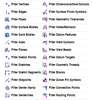
Break Dimension Lines: When the dimension lines are broken, they break around lines that are nearby. If a dimension is moved significantly, it may not break around the new nearby dimensions. To update the display, unbreak the dimension lines and then break them again. To break a dimension line —» select the dimension —» Dimension properties —» select Leaders tab —» select Break Lines —» un-checked Use document gap —» specify the gap (ex: .06) —» check Break extension lines —» un-check Break dimension lines —» OK. However, this would take some time to select them all one by one. The easiest way we found is to use your selection filters command. To break all dimension and extension lines —» select Filter Dimensions/Hole Callouts (1) —» window select all dimensions (2) —» in Dimension —» select Break Lines (3) —» un-check document gap —» enter your prefered gap —» OK.
Conics: The Conic tool lets you sketch conic ((thuộc) hình nón, (thuộc) mặt nón) curves driven by endpoints and Rho value. Depending on the Rho value, the curve can be elliptical, parabolic, or hyperbolic. Conic curves can reference existing sketch or model geometry, or standalone entities. You can dimension the curve with a driving dimension, and the resulting dimension displays the Rho value. The conic entity also includes a value for the radius of curvature. 
Creating Angular Dimension Between Two Lines: Open sketch —» Smart Dimension —» click one line —» Ctrl and click the second line —» move the pointer to show the angular dimension preview —» place the angular dimension —» OK
Horizontal/Vertical Dimensions: Smart Dimension —» select the first feature (radius) —» hold down Shift key —» select the second feature (radius) —» OK
Part Cutaway View: The part cutaway view creates a section in a pictorial/drawing (isometric, trimetric, or dimetric) view. This method relies on part configurations.
‹•› Open a part file, to create a new configuration for the cutaway view —» In FeatureManage Design Tree —» highlight the part name —» select ConfigurationManager —» RMC —» Add Configuration —» Configuration name: (type/enter Cutaway View) —» uncheck Use in bill of material —» OK —»
‹•› In the model (.prt), use Extruded Cut command —» cut the part as it should appear in the drawing view —» 
‹•› In the model (.prt) —» In FeatureManage Design Tree suppress the cut feature in all other configurations —» in the drawing —» select a view —» insert —» drawing view —» projected —» OK —»
‹•› In the drawing (.dwg) —» In FeatureManage Design Tree —» select the inserted view —» RMC —» select Properties —» check Use named configuration —» expand the downward arrow —» select Cutaway View configuration —» OK.
Section View in Drawing: Section View —» select Section/Half Section —» select a Cutting Line —» select Auto-start section view/Use the Section View Popup to add offsets to the Cutting Line —» snap it to the mid-point to pllace the Cutting Line —» LMB to place the Section View (the view should be behind the arrow) —» Section Line direction can be flip using Section View Property —» Section Depth is for Offset Cutting Plane (input a value to offset)
Section view in Model: In a part/assembly document —» select Section View —» Section View Property Manager —» Section Method —» select Planar (to define a section view by selecting one, two, or three planes/planar faces) or Zonal (to define a section view by selecting one or more zones. Zones are defined by the selected plane or face and the bounding box of the model) —» Section Option —» select how the section offset is calculated Reference Plane or Selected Plane —» Section 1 (select a plane) —» set the offset distance and rotation (if the selected is Zonal, you can't reverse the section direction) —» Section 2 and 3 is for model with additional planes or faces —» click Selected bodies or Selected components to create a section view —» Selected components (select Exclude selected or Include selected —» select Enable selection plane —» drag the center ball of trial to view hidden components —» if Zonal under Section Method is selected, select one or more intersection zones —» Preview —» Save —» Save As (View Orientation) —» View Name (SectionView) —» Save.
Sketch Line Color: Options —» System Options —» Colors —» Color scheme settings —» select Sketch Inactive —» Edit (select your preference color) —» OK (to change).
Sketching Line/Midpoint Line: To create a line that is symetrical from the midpoint of the line —» select Midpoint Line —» Insert Line (select As sketched, Horizontal, Vertical, Angle) —» Options (select For Construction, Infinite Length, Midpoint Line, Add Dimensions is for (angle orientation only)) —» OK
Sketching Parabola: Select Parabola ((toán học) đường Pa-ra-bôn). In mathematics, a parabola is a plane curve, which is mirror-symetrical. and is approximately U-shaped when oriented as shown. Parabola —»
Using Centerlines to Create Radial & Diametric Dimensions: In a sketch with a centerline and lines or points, click Smart Dimension —» select the Centerline/Lines/Points —» to create a radius, move the pointer to the near side of the centerline / to create a diameter, move the pointer to the far side of the centerline —» place the dimensions
Using Line Color to Change Color of Features. To change the color of a specific component in a drawing view can be done using Line Color. Switch to drawing —» View —» Toolbars —» select Layer + Line Format —» select a drawing view —» select the lines/features you want to change the color (Ctrl+select) —» (bottom left of screen) select Line Color —» select any color —» OK to change.
View Port Background Color: Options —» System Options —» Colors —» Color scheme settings —» View Port Background Color —» Edit (select your preference color) —» Background appearance —» select Plain (white) —» OK (to change). Default —» select Use document scene background.
HOLE – THREAD – SMART FASTENER
Cosmetic Thread describe the attributes of a specific hole so you need not add real threads to the model. A cosmetic thread represents the minor (inner) diameter of a thread on a boss or the major (outer) diameter of a thread on a hole and can include a hole callout in drawings. Create/Design the part (.prt) without the threaded hole —» select the Hole location surface —» Insert —» Features —» Hole Wizard —» Hole Type —» select Straight Tap —» Standard —» select ANSI Metric —» Type —» select Tapped hole (threaded thru) —» Size —» select size —» End Condition —» select Through All —» Thread —» select Through All —» Options —» check Near side & Far side countersink —» enter countersink diameter and angle —» check/uncheck With thread callout —» select Position tab —» select where to place the thread —» OK.
Cut Thread. Create an Internal Thread —» Create/Design the part (.prt) —» then Insert —» Features —» Hole Wizard —» Hole Type —» select Hole —» Standard —» select ANSI Metric —» Type —» select Drill sizes —» Size —» select a size (should be the thread size) —» OK —» select the thru hole inside diameter edge —» Insert —» Features —» Thread —» End Condition —» select Revolution (type in a number) —» Type —» select Metric/Inch Tap —» Size —» select a size —» Thread Method —» select Cut (internal) or Extrude (external) thread —» Thread Option —» select Right/Left-hand thread —» check Multiple Start (external thread only) and enter 2 or any number to start thread above selected edge) —» check Trim with start face —» check Trim with end face —» Preview Options —» check Shaded/Wireframe preview —» OK.
Hole Series in an Assembly: Creates a series of holes through the individual parts of an assembly. A hole series extends through each unsuppressed part in the assembly that intersects the axis of the hole (the parts don't have to be coinciding).
• – Added parts between the start and end components after the hole series is created. Edit the hole series to update.
• – Depth of hole within each part is the thickness of that part. The depth displayed represents the actual depth of the hole in each part in production drawings.
• – Hole serries parameters of a part can not be edited unless the feature is underive and become a Hole Wizard hole with no reference to the assembly.
NỘI DUNG TÀI TRỢ

Quảng Cáo Dịch Vụ

Quảng Cáo Sự Kiện

Quảng Cáo Khuyến Mãi

Biểu Trưng & Nhãn hiệu
Hỗ trợ chúng tôi và phát triển doanh nghiệp của bạn với chúng tôi. Mục tiêu của tôi là cung cấp thông tin kỹ thuật với khả năng truy cập sẵn sàng vào các tài nguyên, công thức và tài liệu tham khảo thường cần thiết trong khi thực hiện công việc của mình với tư cách là Kỹ sư hỗ trợ kỹ thuật. Các doanh nghiệp được liệt kê trong Nội dung được Tài trợ đã được lựa chọn cẩn thận vì tính độc đáo của chúng. Tuy nhiên, các quảng cáo liệt kê không được tài trợ sẽ được luân chuyển thay đổi hàng tháng.
ViBa Direct thiếu một ban cố vấn để thực hiện nghiên cứu và thuê các nhà văn với kiến thức kỹ thuật hiện đại. Việc tạo ra một ban cố vấn hiệu quả đòi hỏi nhiều hơn là một lời mời. Nếu không có sự tài trợ của bạn, điều này khó có thể thực hiện. Nếu công ty của bạn có nhu cầu quảng cáo, đặt biểu trưng, thương hiệu, biểu ngữ mời tham gia thảnh viên, hội viên cũng như các bích chương quảng cáo ở đây hoặc trên bất kỳ trang nào khác, xin vui lòng liên hệ với nhóm Dịch Vụ Khách Hàng để biết thêm chi tiết.
Create a Hole Series. Suppress the parts in the assembly that will not be cut by the hole. Insert —» Assembly Feature —» Hole —» Hole Series —» set the PropertyManager options by selecting —» Hole Position (select a location/sketch point/planar face) to create a new hole or use an existing hole —» select Hole Series(First Part) —» select Counterbore and fill in values —» select Hole Series(Middle Parts) —» select Hole —» check Auto size based on start hole —» select Hole Series(Last Part) even if the assembly only has two parts —» check Auto size based on start hole —» End component —» select the bottom part —» End Condition (specify value) —» OK to create.
Inserts Smart Fasteners Into The Hole Series —» OK to create.
Replacing Components: Assembly toolbar —» Replace Components —» Multi-site replication allows the sharing of data across multiple locations. This functionality can ensure that all locations have the latest versions of files. EPDM allows the automation and standardization of creating documents, such as ECO’s. Templates can also automatically create a predefined folder structure and automatically name these folders. For example, a folder could be named after project number or customer. EPDM Multiple Workfolws allows a separate workflow for different products, departments and divisions and unlimited Workflow States allows the creation of a workflow that accurately represents a company’s product lifecycle.
Replacing Fasterner Types in Assembly: Design Library —» Bolts and Screws —» select Hex Screw and drag it into the assembly —» select Size + Length —» OK —» Cancel —»select the Inserted Fasterner from the tree —» RMC —» Open Part —» File —» Save —» Save As —» select the folder where the Edit Assembly stored —» Name the Fasterner —» Save —» Close —» In the assembly tree select the fasterner to be replace —» Replace Components —» in Assembly select the fasterner to be replace —» With this one —» Browse —» select a Fasterner to replace —» OK to replace —» Delete the Drag-in Fasterner.
Rename Component Files from Manager Tree On/Off: Allow component files to be renamed from FeatureManager tree —» Tool —» Options —» System Options —» FeatureManager —» select Allow component files to be renamed from FeatureManager Tree —» OK.
SOLIDWORKS ADD-INS and WHAT ARE THEY?
To Access SolidWorks Add-Ins: Tools —» select Add-Ins. Within the Add-Ins dialog, we have the option of making the Add-In active in the current session (Active Add-Ins, the left column of checkboxes) and we can also select which Add-Ins to automatically enable when SOLIDWORKS launches (Start Up, the right column of checkboxes). Some of the Add-Ins required license.
SolidWorks Design Checker: The Design Checker is a utility that verifies settings in a document such as dimension standards, annotation settings, fonts, materials, units, ect. The SOLIDWORKS Design Checker is an add-in that is available in SOLIDWORKS Premium and SOLIDWORKS Professional only. Tools —» Design Checker —» Build Checks (use this tool to set the requirements for evaluation) or Learn Check Wizard (use this tool to retrieve design checks based on attributes from an existing SOLIDWORKS document) or Check Active Document (use this tool to validate the current document or Check Against Existing File (use this tool to validate the active document against design checks from existing files) —» Laumch the Check Active Document, in Design Checker Task Pane —» click + (to add a new standards file, – to remove from the list) —» check on of the boxes to select an existing standard to run on the active document —» select File to open a document to check Tools —» Options —» System Options —» File Locations —» select Design Checker in the pull down menu —» Add the path to the folder location that contains the .swstd files
SolidWorks Utilities: Utilities is a significant productivity tool. Utilities finds differences between two versions of the same part quickly and identifies problematic geometry in a part. It can also find, modify, and suppress feature within a model. Specific functionality includes:
‹•› Thickness Analysis: Determines thin and thick regions of a part and the thickness of a part within a specified range of values.
‹•› Compare Geometry: Enables you to quickly determine what geometry is different between two designs using Face Comparison, Geometry Comparison, or View Synchronisation
‹•› Compare Features: Highlights what model features are different between two designs and color-codes them from easy identification. A list of differences can be generated
‹•› Compare BOMs: Compares bill of material (BOM) tables from two SOLIDWORKS assembly or drawing documents, listing missing columns and rows, extra columns and rows, and failed rows.
‹•› Compare Document: Allows you to easily compare the properties of 2 SOLIDWORKS documents. Any standard hole types, such as simple, tapered, and counterbored
NỘI DUNG TÀI TRỢ
Your Service Flyer
Your Event Invitation
Your Promotion Ads
Your Logo & Brand
‹•› Geometry Analysis: Helps you identify and highlight problematic imported geometry in a part based on user-specified parameters such as minimum fillet radius, minimum sliver face size, etc.
‹•› Find/Modify: Finds a set of features in a part that satisfy specified parameter conditions and edits them in a batch mode.
‹•› Symmetry Check: Checks automatically for geometric symmetry in parts and assemblies about a plane and identifies symmetrical, asymmetrical, and unique faces. Automatic Symmetry Check reduces a part to its smallest repeatable symmetrical body—especially useful when running analyses using simulation software.
‹•› Report Manager: Manages reports generated by the Geometry Analysis, Compare Geometry, Compare Features, Compare Documents, Compare BOMs, Symmetry Check, and Thickness Analysis utilities.
‹•› Report Manager: Manages reports generated by the Geometry Analysis, Compare Geometry, Compare Features, Compare Documents, Compare BOMs, Symmetry Check, and Thickness Analysis utilities.
‹•› Power Editing: Lets you find, modify, and suppress features within a model based on their parameters. Power editing also lets you create simplified versions of parts and assemblies by locating and suppressing small features
TOOL BOX SETUP & UPGRADING
The Toolbox is a collection of several powerful tools built into SolidWorks. Its can increase productivity and decrease the time required to complete a design. These components can be configured to easily populate Bills of Material with part numbers, descriptions or any other custom information that needs to be easily displayed to the user. The toolbox can populate bills of material, contain materials, and automatically be added to assemblies. These functions, though powerful, must be configured up by the user(s).
Toolbox Settings: The toolbox has a variety of settings that require configuration for the best utilization of the toolbox program. These control how the toolbox functions internally along with what data will be displayed to the user while they utilize the toolbox inside of solidworks. To edit the settings associated with toolbox launch the toolbox settings program ( or choose configure toolbox inside of Solidworks) and select option 3 “Define user settings”. The first major setting is whether toolbox will create parts or configurations when hardware of a new configuration is used. This is an internal setting and will not change how the user interacts with the toolbox utility.
‹•› Create Configurations will add a new configuration (cấu hình) to an existing toolbox file each time a new toolbox size is used. This will lead to very large files with a large number of configurations. This setting can see reduced performance in large assemblies.
‹•› Create Parts will create a library of files each, file representing a single configuration of a toolbox file with a single specific size. This setting will create a large volume of part files but each of these will have a very small file size.
‹•› Create Parts on Ctrl-Drag is a hybrid of the two versions previously mentioned, it will act like create configurations except for when users press CTRL while dragging components onto the screen.
Convert Toolbox Part Into a Solidworks Part. To save a component (ex: pan head screw) within an assembly —» In an assembly —» Design Library —» Bolts and Screws —» Machine Screws » select Pan Cross Head —» drag and drop into the assembly —» select the screw size —» OK to insert —» select the screw —» RMC and select Open Part —» OK to make the change —» File —» Save As —» Save As —» save to the folder where the assembly is saved —» name the screw —» Save. Altenative method is to use the Pack and Go function to save all the components used in the assembly.
Using Line Color to Change Color of Features. Changing component colors in drawing view. To change the color of a specific component in a drawing view can be done using Line Color. Switch to drawing —» View —» Toolbars —» select Layer + Line Format —» select a drawing view —» select the lines/features you want to change the color (Ctrl+select) —» (bottom left of screen) select Line Color —» select any color —» OK to change.


