|
|
GD&T FUNDAMENTALS – ASME ANSI Y14.5-2018
The names and definitions of many GD&T terms have very specific meanings. To be able to function, it is important for each GD&T practitioner to be very familiar with these terms.
Geometric Dimensioning and Tolerancing is a symbolic language used to specify the SIZE | SHAPE | FORM | ORIENTATION | LOCATION of features on a part. A means of dimensioning and tolerancing a part with respect to the relationship and function of that part. Features toleranced with GD&T are used to define how a part feature relates to the other part features in the same part or in a mating part; it’s a way to dimension and tolerance with respect to the part’s function, and the way it works.
ASME Y14.5-2018 is the current, authoritative reference document that specifies the proper application of GD& T. GD& T was designed to ensure the proper assembly of mating parts, improve quality, and reduce cost.
GD&D Basic: A convenient guide for Geometric Dimensioning and Tolerancing fundamentals at your fingertips.
‹•› If CAD/CAM database 3D models are used and they do not include tolerances, tolerance values may be expressed in a 2D detailed drawing or product definition data set.
‹•› The drawing should define the part without specifying manufacturing methods.
‹•› Dimensions shall not be subject to more than one interpretation.
‹•› All tolerances apply for the full length, width, and full depth of the feature unless otherwise specified.
‹•› Dimensions and tolerances apply only at the drawing level where they are specified.
‹•› Dimensioning and tolerancing must be complete so there is a full understanding of the characteristics of each feature.
‹•› Each dimension shall have a tolerance except those dimensions specifically identified as a reference, maximum, or stock.
‹•› Units of linear measurement are typically expressed either in the inch system or the metric system.
‹•› For decimal inch tolerances, a zero is never placed before the decimal point for values less than one inch. Ex: .75, not 0.75.
‹•› For decimal inch tolerances, where bilateral tolerancing or limit dimensioning and tolerancing are used, both values have the same number of decimal places.
‹•› For decimal inch tolerances, where a unilateral tolerance is specified and either the plus (+) or minus (-) limit is zero, the zero value will have the same number of decimal places as the other limit, and the appropriate plus (+.510) and minus (-.495) sign.
‹•› For decimal inch tolerances, a dimension is specified with the same number of decimal places as its tolerance. Ex: 1.250 ±.005.
‹•› Dimensional limits are used as if an infinite number of zeros followed the last digit after the decimal point.
‹•› All dimensions and tolerances apply in the free state condition except for non-rigid parts. Angular units of measurement are specified either in degrees and decimal parts of a degree, or degree (°), minutes(’), and second (“).Ex: 15°30’45“.
‹•› A 90° angle applies where center lines and lines depicting features are shown on a 2D orthographic drawing at right angles and no angle is specified.
‹•› A basic 90° angle applies where centerlines of features in a pattern or surfaces shown at right angles on a 2D orthographic drawing are located or defined by basic dimensions and no angle is specified.
‹•› The two dimensions not placed on the field of the drawing are the 90° angle and a zero.
‹•› All dimensions and tolerances are applicable at 68° F (20° C) unless otherwise specified. Measurements made at other temperatures may be adjusted mathematically.
RULES, TERMS, AND SYMBOLS
Actual local size is the measurement where you measure it (local size). Atual mating envelope is the shape of a perfect form that encompasses (bao quanh) the actual feature. Actual values are derived (lấy được từ) from actual parts. One cylindrical or spherical surface, or a set of two opposed (tương phản với) elements or opposed parallel surfaces, associated with a size dimension. The condition in which a feature of size contains the maximum amount of material within the stated limits if size, for example, minimum hole diameter, maximum shaft diameter.
Free State: 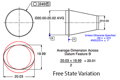 The condition of a part free of applied forces. Use the free state symbol for plastic, sheet metal and other flexible parts. In section 1.4 FUNDAMENTAL RULES of Y14.5-2009 paragraph (m) stated "Unless otherwise specified, all dimensions and tolerances apply in a free-state condition. This principle does not apply to nonrigid parts...Where the actual local size of a regular feature of size has departed from MMC toward LMC, a local variation in form is allowed equal to the amount of such departure". The default, then, is that all parts are considered rigid unless there is some indication that the part may be flexed or distorted for inspection. A way to indicate that a part is not rigid is to add a constraint note. If some tolerances are to be checked with the part not constrained, the free state symbol may be added to specific tolerances. Many usable sheet metal and plastic parts will pass inspection and be functional if clamped to a condition that simulates the assembled or functionale state. Usually when a constraint note is applied to a drawing, at least one tolerance should be inspected in the free state to limit the free state variation.
Allowance: Difference between the MMC of two mating parts. (Minimum clearance and maximum interference)
SPONSORED CONTENT

Your Service Flyer

Your Event Invitation

Your Promotion Ads

Your Logo & Brand
Support us and grow your business with us. My goal was to make technical information available with ready access to commonly needed resources, formulas, and reference materials while performing my work as a Technical Support Engineer. The businesses listed in the Sponsored Content section were randomly selected because of their uniqueness. However, non-sponsored selected ads will be rotated monthly.
Viba Direct lacks an advisory board to do research and hire writers with the latest technological knowledge. Creating an effective advisory board requires more than an invitation. Without your sponsorship, this is not possible. If your company is interested in placing the company's logo, brand, event invitation, and other promotional banners and flyers here or on any other pages. Please Customer Service for more detail.
Actual Mating Envelope (AME): Actual mating envelope is a term that refers to a machined or manufactured part’s feature of size “as is” condition. The actual mating envelope is a surface, or pair of parallel-plane surfaces, of perfect form, which correspond to a part feature of size as described below —»
‹•› External Feature: A similar perfect feature counterpart of smallest size, which can be circumscribed (vẽ hình ngoại tiếp) about the feature so that it just contacts the feature surfaces(s)
‹•› Internal Feature: A similar perfect feature counterpart of largest size, which can be inscribed (vẽ hình nội tiếp) within the feature so that it just contacts the feature surfaces(s)
Basic Dimension: Nominal dimension from which tolerances are derived. A theoretically exact size, profile, orientation, or location of a feature or datum target, therefore, a basic dimension is untoleranced.
Clearance Fit: A fit type where clearance exists between assembled parts under all tolerance conditions.
Datum: Datums are features (points, axis, and planes) on the object that are used as reference surfaces from which other measurements are made. Used in designing, tooling, manufacturing, inspecting, and assembling components and sub-assemblies. Always start with the letter A. Do not use letters I, O, or Q. Datums must be perpendicular to each other.
Deviation: The difference between a size and the corresponding nominal size.
Interference Fit: A fit type where interference exists between assembled parts under all tolerance conditions.
Limit of Size: A variation in form is allowed between the least material condition (LMC) and the maximum material condition (MMC). The actual size of the feature at any cross section must be within the size boundary. No portion of the feature may be outside a perfect form barrier at maximum material condition (MMC).
LMC (Least Material Condition: The condition where a size feature contains the least amount of material within the stated limits of size. I.e., smallest shaft and largest hole.
Lower deviation: The difference between the minimum limiting size and the corresponding nominal size of a feature.
NỘI DUNG TÀI TRỢ

Quảng Cáo Dịch Vụ

Quảng Cáo Sự Kiện

Quảng Cáo Khuyến Mãi

Biểu Trưng & Nhãn hiệu
Hỗ trợ chúng tôi và phát triển doanh nghiệp của bạn với chúng tôi. Mục tiêu của tôi là cung cấp thông tin kỹ thuật với khả năng truy cập sẵn sàng vào các tài nguyên, công thức và tài liệu tham khảo thường cần thiết trong khi thực hiện công việc của mình với tư cách là Kỹ sư hỗ trợ kỹ thuật. Các doanh nghiệp được liệt kê trong Nội dung được Tài trợ đã được lựa chọn cẩn thận vì tính độc đáo của chúng. Tuy nhiên, các quảng cáo liệt kê không được tài trợ sẽ được luân chuyển thay đổi hàng tháng.
ViBa Direct thiếu một ban cố vấn để thực hiện nghiên cứu và thuê các nhà văn với kiến thức kỹ thuật hiện đại. Việc tạo ra một ban cố vấn hiệu quả đòi hỏi nhiều hơn là một lời mời. Nếu không có sự tài trợ của bạn, điều này khó có thể thực hiện. Nếu công ty của bạn có nhu cầu quảng cáo, đặt biểu trưng, thương hiệu, biểu ngữ mời tham gia thảnh viên, hội viên cũng như các bích chương quảng cáo ở đây hoặc trên bất kỳ trang nào khác, xin vui lòng liên hệ Dịch Vụ Khách Hàng Dịch Vụ Khách Hàng để biết thêm chi tiết.
MMC (Maximum Material Condition: The condition where a size feature contains the maximum amount of material within the stated limits of size. I.e., largest shaft and smallest hole.
Nominal Size: The size of a feature of perfect form as defined by the technical drawing.
Primary Datum: A primary datum is selected to provide functional relationships, accessibility, and repeatability. A primary datum is choosen to reference the location of the mating features. Consider how parts are orientated to each other is very important. The surface established must produce consistent. The primary datum chosen must insure precise measurements. The surface established must produce consistent measurement and repeatability when producing many identical parts to meet requirements specified.
Second and Tertiary Datums: All dimension may not be capable to reference from the primary datum to ensure functional relationships, accessibility, and repeatability. Secondary datums are produced perpendicular to the primary datum so measurements can be referenced from them. Tertiary datum is always perpendicular to both the primary and secondary datums ensuring a fixed position from three related parts.
Tolerance: The difference between the maximum and minimum size limits of a part. Or the difference between MMC and LMC limits of a single dimension.
Transition Fit: A fit type where clearance or interference can exist between assembled parts depending on tolerance conditions.
Upper deviation: The difference between the maximum limiting size and the corresponding nominal size of a feature.
ACTUAL LOCAL SIZE and ACTUAL MATING ENVELOPE
Actual local size is the measurement where you measure it (local size). Atual mating envelope is the shape of a perfect form that encompasses (bao quanh) the actual feature. Actual values are derived (lấy được từ) from actual parts. One cylindrical or spherical surface, or a set of two opposed (tương phản với) elements or opposed parallel surfaces, associated with a size dimension. The condition in which a feature of size contains the maximum amount of material within the stated limits if size, for example, minimum hole diameter, maximum shaft diameter.
The actual mating envelope is the shape of a perfect form that encompasses (bao quanh) the actual feature. The actual mating envelope is a similar, perfect, feature(s) counterpart (tương ứng, đối tác, đối chiếu) of smallest size that can be contracted (rút gọn) about an external feature(s) or largest size that can be expanded within an internal feature(s) so that it coincides with the surface(s) at the highest points. It's the smallest perfect shape that will fit around an external Feature of Size or the largest perfect shape that will fit inside an internal Feature of Size. Two types of actual mating envelopes are described below.
SPONSORED CONTENT
Your Service Flyer
Your Event Invitation
Your Promotion Ads
Your Logo & Brand
‹•› Unrelated Actual Mating Envelope: The size of the Unrelated Actual Mating Envelope is considered to be the size of the pin. The axis of the Unrelated Actual Mating Envelope is considered to be the axis of the pin. An unrelated actual mating envelope is a similar perfect feature(s) counterpart contracted about an external feature(s) or expanded within an internal feature(s), and not constrained to any datum feature(s).
‹•› Related Actual Mating Envelope: The Related Actual Mating Envelope is always perpendicular to the datum. A related actual mating envelope is a similar perfect feature(s) counterpart contracted about an external feature(s) or expanded within an internal feature(s) while constrained either by an orientation or location control or both to the applicable datum feature(s).
* Note: The Actual Mating Envelope must be oriented relative to the specified Datums. When an inspector merely uses the size of a feature to calculate the bonus tolerance, out of spec parts may be accepted. 
‹•› Example: On the drawing, a hole call-out Ø.500 +.004/-.001 at True Position Ø.015 at MMC to Datums A, B, and C. On the finish part, it's measured .502. It would be incorrect to use a bonus tolerance of .003 (.502-.499 (MMC)) if the hole is not perfectly oriented to the Datums. If the hole is out of perpendicular to datum A by .002, for instance, the bonus that may be used is reduced by that amount. The bonus would be merely .001 and the allowable position tolerance is .016.
DIMENSION and BASIC DIMENSION
Dimension: Is the numerical value that defines the size or geometric characteristic of a feature.
Basic Dimension: Title block tolerances do not apply to basic dimensions. The tolerance associated with a basic dimension usually appears in a feature control frame or a note. A basic dimension is a theoretically (về lý thuyết mà nói, về mặt lý thuyết) exact dimension. Basic dimensions define the true position of the toleranced Feature os Fize (FOS) relative to the datums referenced in the feature control frame. In certain cases, the basic dimensions in a TOP application are not specified; they are implied. There are two types of implied (ngụ ý, bao hàm) basic dimensions common in TOP applications:
- Implied basic 90° angles —» A 90° basic angle applies where centerlines of features in a pattern (or surfaces shown at right angles on a drawing) are located and defined by basic dimensions and no angle is specified.
- Implied basic zero dimension —» Where a centerline or centerplane of a FOS is shown in line with a datum axis or centerplane, the distance between the centerlines or centerplanes is an implied basic zero. The view implies the relationship of the Ø.750 hole to the planes of the DRF as represented by the view's center lines. Obviously, the hole's basic orientation is 0° and its basic offset from center is 0. These implied zero-basic values need not be explicated (giải nghĩa, giải thích).
Reference Dimension: Is the numerical value enclosed in parentheses provided for information only and is not used in the fabrication of the part.
Plus and Minus Dimensioning: Is the allowable positive and negative variance from the dimension specified.
Limits of Size: Is the largest acceptable size and the minimum acceptable size of a feature.
‹•› The largest acceptable size is expressed as the (MMC) maximum material condition.
‹•› The smallest acceptable size is expressed as the (LMC) least material condition.
WHAT IS BONUS TOLERANCE?
 Bonus tolerances can reduce manufacturing costs significantly. Bonus tolerance is an additional tolerance for a geometric control. Whenever a geometric tolerance is applied to a feature of size, and it contains an MMC (or LMC) modifier in the tolerance portion of the feature control frame, a bonus tolerance is permissible.
‹•› Based on MMC Modifier: It means that the stated tolerance applies when the feature of size is at its MAXIMUM MATERIAL CONDITION.
As the actual mating envelope size of the feature departs from MMC toward LMC, a bonus tolerance is achieved in the exact amount of such departure.
Bonus tolerance equals the difference between the actual mating envelope and the MMC sizes of a feature. The bonus tolerance is added to the geometric tolerance specified in the feature control frame. Of the three material condition modifiers, the MMC modifier is the most common and is typically used for features on parts that are to be fastened together in a static assembly.
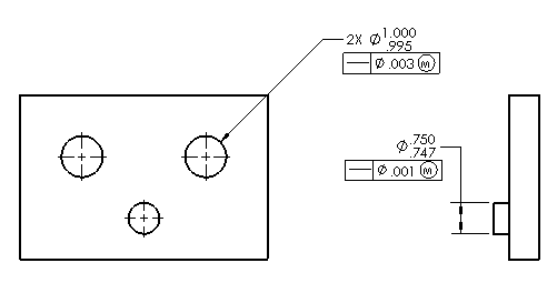
Bonus Tolerance Applies to An Internal Feature: Example of a hole with a diameter 1.000/.995 and having a straightness at MMC as .003. If actual size is —»
‹•› 1.000 = .005 is bonus tolerance | .998 = .002 is bonus tolerance | .996 = .001 is bonus tolerance | 1.000 (LMC) = Bonus tolerance is .0 (maximum tolerance).
Bonus Tolerance Applies to An External Feature: Example of a pin with a diameter .750/.747 and having a straightness at MMC as .001. If actual size is —»
‹•› .750 = 0 is bonus tolerance | 749 = .001 is bonus tolerance | .748 = .002 is bonus tolerance | .747 (LMC) = Bonus tolerance is .003 (maximum tolerance).
DEGREES OF FREEDOM — DATUM AND DATUM FEATURE
Degrees of Freedom: (page 5-72)...developing subject.
Six Degrees of Freedom: 6DoF refers to the freedom of movement of a rigid body in three-dimensional space. Specifically, the body is free to move forward/backward, up/down, left/right (translation in three perpendicular axes) combined with rotation about three perpendicular axes, often termed pitch, yaw, and roll.
Datum: A datum is a theoretically exact point, axis, line, plane, or combination thereof derived from the theoretical datum feature simulator (used as a reference for tabular dimensioning). A datum is the origin from which the location or geometric characteristics of features of a part are established.
‹•› Tabular Dimensioning: A form of arrowless dimensioning in which dimensions to features are shown on a table.
Chart Dimensioning: A unidirectional, aligned, arrowless, or tabular dimensioned drawing used when dimensions change values.
Implied Datum: An assumed plane, axis, or point drom which a dimensional measurement is made.
Datum Feature: A datum feature is a feature that is identified with either a datum feature symbol or a datum target symbol (page 5-61).
Datum Feature Selection: (page 5-61).....developing subject.
Datum Feature Simulator (Theoretical): A datum feature simulator (Theoretical) is the theoretically perfect boundary used to establish a datum from a specified datum feature.
Datum Feature Simulator (Physical): A datum feature simulator (Physical) is the physical boundary used to establish a simulated datum from a specified datum feature. Physical datum feature simulators are represented by inspection or manufacturing tooling
Datum Reference Frame: A datum reference frame consists of three mutually perpendicular intersecting datum planes.
True Geometric Counterpart or TGC: (page 5-67)...developing subject.
DERIVED ELEMENTS
Derived Elements: A multitude of geometric elements can be derived from any feature. A geometric tolerance RFS applied to a feature of size controls one of these five.
‹•› Derived (xuất phát từ, chuyển hoá từ, bắt nguồn từ) median (ở giữa) line (from a cylindrical feature) 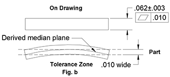
‹•› Derived median plane (from a width-type feature)
Feature center point (from a spherical feature)
Feature axis (from a cylindrical feature)
Feature center plane (from a width-type feature)
A Level 2 (straightness or flatness) tolerance nulifies (huỷ bỏ; làm thành vô hiệu) Rule #1's boundary of perfect form at MMC. Instead, the separate tolerance controls overall feature from constraining the derived median line or derived median plane, according to the type of feature.
A cylindrical feature's derived median line is an imperfect line (abstract) that passes through the center points of all cross sections of the feature. These cross sections are normal to the axis of the actual mating envelope. The cross section center points are determined as per ANSI B89.3.1. 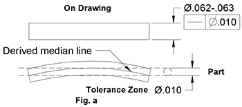
A width-type feature's derived median plane is an imperfect plane (abstract) that passes through the center points of all line segments bounded by the feature. These line segments are normal to the actual mating envelope.
Tolerance zone for straightness control RFS. In Fig. a, the absence of a material condition modifier symbol means the straightness tolerance applies RFS by default. This specifies a tolerance zone bounded by a cylinder having a diameter equal to the tolerance value, within which the derived median line shall be contained.
Tolerance zone for flaness control RFS. In Fig. b, the flaness tolerance applies RFS by default. This specifies a tolerance zone bounded by two parallel planes separated by a distance equal to the tolerance value, within which the entire derived median plane shall be contained. Both size limits are still in force, but neither the spine for the MMC size boundary nor the spine for the LMC size boundary need be perfectly formed. A straightness or flatness tolerance value may be less than, equal to, or greater than the size tolerance.
FEATURE AND FEATURE OF SIZE
Feature: A feature is a physical portion of a part, such as a surface, pin, hole, tab, slot, or its representation on drawings, models, or digital data files.
Feature of Size: A feature of size encompasses two types.
Regular Feature of Size: A regular feature of size is a feature, which is associated with a directly toleranced dimension and takes one of the following forms:
‹•› A cylindrical surface • A set of two opposed parallel surfaces • A spherical surface • A circular element • A set of two opposed parallel elements.
Irregular Feature of Size: The two types of irregular feature of size are:
‹•› A directly toleranced feature or collection of features that may contain or be contained by an actual mating envelope that is a sphere, cylinder, or pair of parallel planes.
‹•› A directly toleranced feature or collection of features that may contain or be contained by an actual mating envelope other than a sphere, cylinder, or pair of parallel planes.
LIMITS OF SIZE (MMC) AND (LMC)
Maximum Material Condition (MMC): The maximum material condition is the condition in which a feature of size contains the maximum amount of material within the stated limits of size. For example, the minimum hole diameter/slot width and the maximum pin/shaft diameter.
Least Material Condition (LMC): The least material condition is the condition in which a feature of size contains the least amount of material within the stated limits of size. For example, the maximum hole diameter/slot width and the minimum pin/shaft diameter.
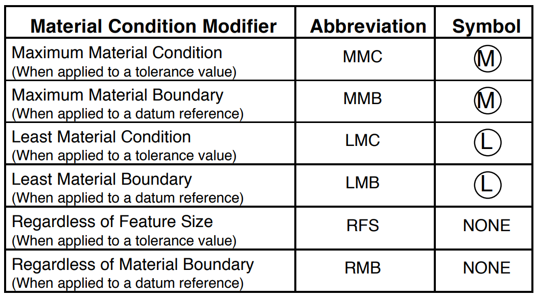
MATERIAL CONDITION MODIFIERS
A material condition modifier is specified in a feature control frame, associated with the geometric tolerance of a feature of size or a datum feature of size. The material condition modifiers are shown in the table and figure below.
TRUE POSITION AND TRUE PROFILE
True Position: True position is the theoretically exact location of a feature of size, as established by basic dimensions. 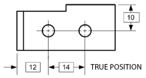 Expressed as the total permissible variation that a feature can have from its “true” position. Depending on how it is called out, true position can mean several different things. It can be used with MMC (Max Material Condition), LMC (Least Material Condition), projected tolerances (P), and tangent planes (T). Tolerance zones are located at true position (examples).
True Profile: True profile is the theoretically exact profile on a drawing defined by basic dimensions or a digital data file. Tolerance zones are located about the true profile.
Resultant Condition: The resultant condition (điều kiện tổng hợp) is the state of a toleranced feature at the other boundary (ranh giới), the boundary the design engineer believes they care less about. Obviously, the design engineer must be cognizant (biết, hiểu biết, biết rõ) of both the MMB and LMB for every feature, but in many cases, there is one boundary that is more functionally significant. The resultant condition of a feature of size specified with a MMC modifier is the single worst-case boundary generated by the collective effects of the LMC limit of size, the specified geometric tolerance, and the size tolerance. The size tolerance is the bonus tolerance at LMC. Features specified with a least material condition modifier also have a resultant condition.
Resultant condition calculations for features toleranced at MMC:
‹•› External Features (Pin/Shaft): LMC — Minus Geometric Tolerance @ MMC — Minus The Size Tolerance (Bonus) / Divided Resultant Condition
Internal Features (Hole): LMC + Plus Geometric Tolerance @ MMC + Plus The Size Tolerance (Bonus) / Divided Resultant Condition
For a part dimensioned and toleranced in accordance with ASME Y14.5, the resultant condition is either:
‹•› The sum or difference of the size, size tolerance, the geometric tolerance at the specified material condition, and the additional (bonus) tolerance for the opposite material condition, or
The sum or difference of the size, size tolerance, the geometric tolerance at the specified material condition, and the allowable form error at the other material condition, or some combination of these.
VIRTUAL CONDITION
Virtual Condition is the boundary generated by the collective effects of MMC, size limit of a feature and any associated geometric tolerance, virtual condition must be considered in determining the fit between mating parts. Features specified with a least material condition modifier also have a virtual condition (virtual size). Virtual Condition of the Hole is .992 and Virtual Condition of the Pin is ,751
‹•› Internal Features (Hole/Slot): Determine Feature MMC Value (Smallest is .995) —» GD&T Tolerance Value – MMC = Virtual Condition Value (Ex: A hole with a diameter 1.000/.995 and a straightness tolerance .003 specified at MMC, the virtual condition would be .992).
External Features (Pin/Shaft): Determine Feature MMC Value (Largest is .750) —» GD&T Tolerance Value + MMC = Virtual Condition Value (Ex: A pin with diameter .750/.474 and a Straightness tolerance .001 is specified at MMC, the virual condition/extreme boundary would be .751).
WORST CASE BOUNDARY
The worst-case boundary of a feature is a general term that describes the smallest or largest boundary generated by the collective effects of the MMC or LMC of a feature and any applicable geometric tolerance.
‹•› Inner boundary specified at MMC: The worst-case inner boundary is the virtual condition of an internal feature and the resultant condition of an external feature.
‹•› Outer boundary specified at MMC: The worst-case outer boundary is the resultant condition of an internal feature and the virtual condition of an external feature.
Features specified with an LMC modifier also have worst-case boundaries.....developing subject.
Your Support Can Help Us Grow. Thank you for visiting ViBa Direct. As part of our commitment to continually improving the visitor experience, we’re doing our best to add the latest information with ready access to commonly needed resources, engineering, formulas, reference materials, photography, and travel. Unfortunately, we don't have enough manpower to meet everyone's needs. But if you are interested in helping us with the site maintenance cost. Please mail your donation to ViBa Direct., P.O. Box 1801., Pflugerville, TX 78691. Thank you for taking the time to read this. Feel free to Customer Service with any additional feedback you would like to share about your experience visiting ViBaDirect.com


