|
|
HOW DOES POSTITION TOLERANCE APPLIED TO FOS?
A Position Tolerance at RFS Applied to A Hole: What does a position tolerance at RFS specified on a size dimension of a hole apply to? The axis of the unrelated actual mating envelope of the hole. A Position Tolerance at RFS Applied to A Slot:
A Position Tolerance at MMC Applied to A Round Slot: There are two ways to properly GTOL a rounded slot. The easiest method for engineers to grasp is to unidirectionally position tolerance each of the slots features of size—this is the non-preferred method (see Fig. 1.a). It is non-preferred because it leaves a lot of room for weirdness with the radii. The second way is to use a Profile of Surface to control the slot size in combination with the Position tolerance to control location—this is the preferred method (see Fig. 1.b).
A Position Tolerance at RFS Applied to Coaxial Diameters: The axis of the toleranced diameter must be within the tolerance zone cylinder centered about datum axis A.
A Position Tolerance RFS Applied to A Pattern of Holes: The axis of each hole (RFS) must be within the tolerance zone. The orientation of the axis of each hole (RFS) is also limited by the tolerance zone cylinders.
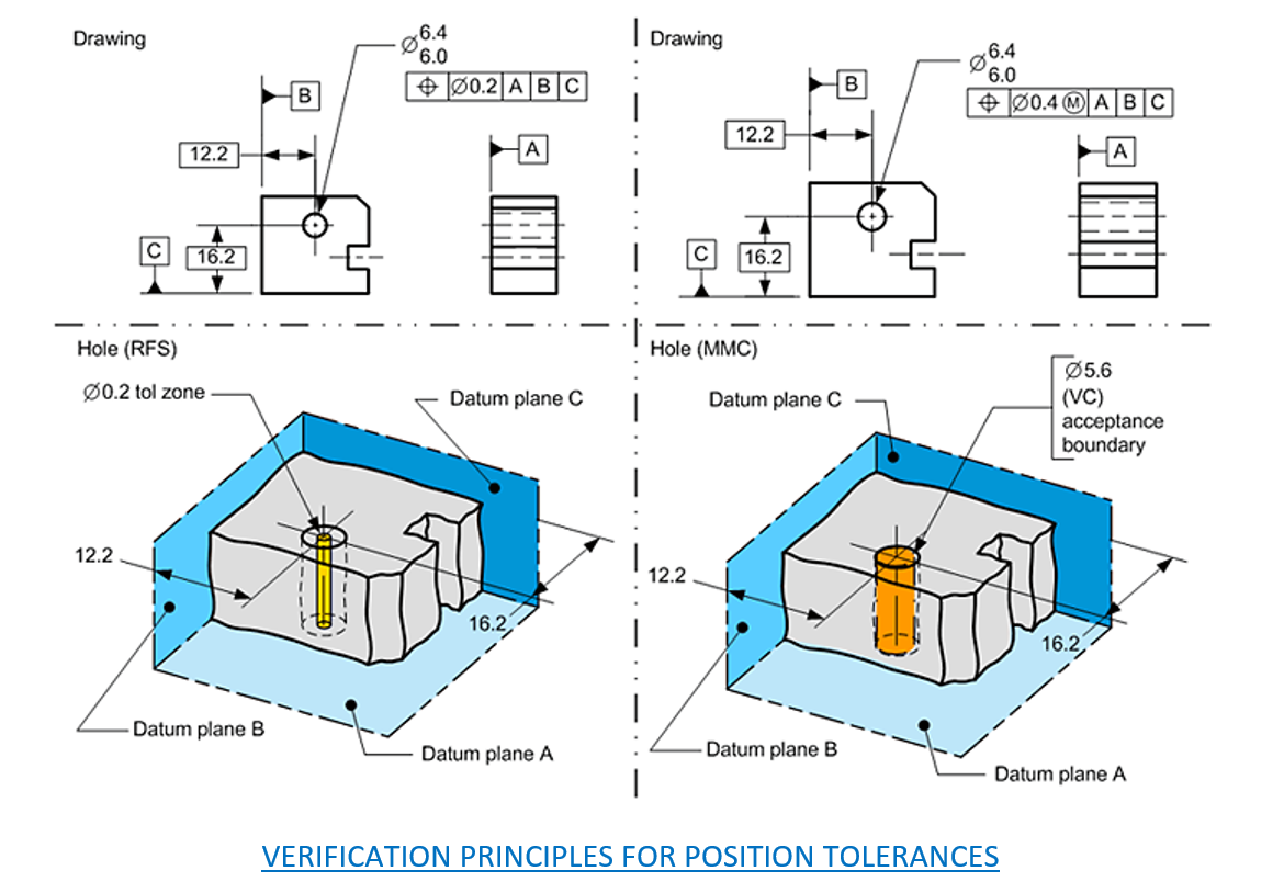
A Position Tolerance at MMC Applied to A Hole: Which is a condition of applying a position toilerance at MMC to the size dimension of a hole? The tolerance zone is a virtual condition acceptance boundary.
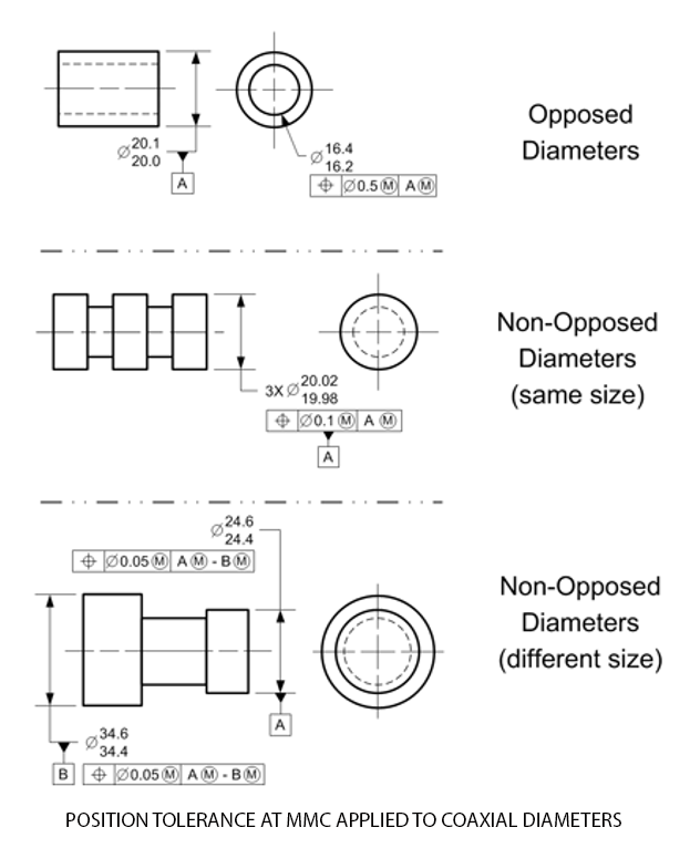
Position Tolerance at MMC Applied to Coaxial Diameters: When a position tolerance is applied to oppose coaxial diameters, a datum reference should be specified in the feature control frame. When a position tolerance is applied to non-opposed same size coaxial diameters, a datum reference should not be specified in the feature control frame. Position tolerance applied to non-opposed different size coaxial diameters.
Postion Tolerance at MMC Applied to A Pattern of Holes: When a postion tolerance at MMC is applied to a pattern of holes, it controls deviations in location, orientation and spacing. The surface of the holes cannot be within the virtual condition acceptance boundaries. The orientation of the axis of each hole is also limited by the virtual condition acceptance boundary.
UNDERSTAND THE VERIFICATION PRINCIPLES FOR POSTION TOLERANCES


