GD&T & TYPES OF DIMENSIONING – ANSI Y14.5
An engineering drawing may communicate the following:
‹•› Geometry of the part
‹•› Critical functional relationship
‹•› Tolerances
‹•› Material, heat treat, surface coatings
‹•› Part documentation such as part number and drawing revision
Drawing errors compound the cost of the errors (money, time, material, and customer satisfaction) as we move further from initial design to production.  Drawing errors create Disagreements over drawing interpretation –» Difficulty communicating drawing requirements –» and Designer's intent can not be understood.
Dimensions: A numerical value expressed in appropriate units of measure and used to define the size, location, orientation, form or other geometric characteristics of a part. Decimal dimensioning shall be used on mechanical drawing. The follwing shall be observed where specifying millimeter dimensions used on drawings.
Metric Dimension Notes: Drawing must state the units used and certain other information used in the drawing: ALL DIMENSIONS IN MILLIMETRES UNLESS STATEE OTHERWISE –» DRAWING IN ACCORDANCE WITH THE STANDARD REFERENCED IN BS8888: 2004 –» COMPONENTS/PARTS TO BE STAMPED WITH THEIR PLANT IDENT NUMBER WHERE MARKED/SHOWN IN LETTERS AT LEEAST 3MM HIGH.
Metric Dimensioning:
‹•› When a metric dimension is a whole number; the decimal point and zero are omitted (Ex: .27). If dimension is a whole number, neither the decimal point or a zero is shown (14).
‹•› When a metric dimension is less than one mllimeter, a zero precedes the decimal point Ex:0.5). If dimension is less than 1 mil, a zero precedes the decimal point (0.5).
‹•› When a metric dimension is not a whole number; a decimal point with the portion of a millimeter (10ths or 100ths) is specified (Ex: 11.5). If the dimension exceeds a whole number by a decimal fraction of 1 mil, the last digit to the right of the decimal point is not followed by a zero (ø14.2).
Deviation (độ lệch): The difference between a size and the corresponding nominal size.
Inch Dimensioning: A zero is not used before the decimal point for value less than 1" (.214). Tolerance should be expressed with the same number of decimal places as its dimensioned (1.234 ±.005 or .24 ±.01 ).  Where unilateral tolerancing is used and either the +/- value is nil, its dimension shall be expressed with the same number of decimal places.
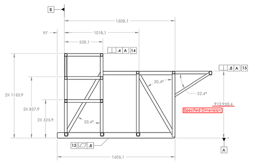
Specified Dimension is the target dimension from which the limits are calculated.
Dimensioning Limits: All dimensioning limts are absolute. That is all dimensions are considered to have a zero after the last true digit (Ex: 1.62 means 1.620.
Deviation (độ lệch): The difference between a size and the corresponding nominal size.
Upper Deviation: The difference between the maximum limiting size and the corresponding nominal size of a feature.
Lower Deviation: The difference between the minimum limiting size and the corresponding nominal size of a feature.
Tolerance: Tolerance is the total permissible variation of a size. The difference between the maximum and minimum size limits of a part.
Actual Fit: The actual fit between two mating parts is the raltion existing between them with respect to the amount of clearance or interference that is present when they're assembled.
Clearance Fit: A fit type where clearance exists between assembled parts under all tolerance conditions. A clearance fit (khoảng hở, độ hở) is one having limits of size so when provided or specified that a clearance always results when mating part are assembled.
Interference Fit: A fit type where interference exists between assembled parts under all tolerance conditions. An interference fit (chạm vào nhau) is one having limits of size so when provided or specified that an interference always results when mating parts are assembled.
Transition Fit: A fit type where clearance or interference can exist between assembled parts depending on tolerance conditions. A transition fit is one having limits of size so when provided or specified that either a clearance or an interference may result when mating parts are assembled.
TOLERANCE AND TYPES OF TOLERANCES
ANSI/ASME Standard Y14.5 . Each dimension shall have a tolerance, except those dimensions specically identified as reference, maximum, minimum, or stock.  A tolerance is an acceptable amount of dimensional variation that will still allow an object to function correctly. The tolerance may be applied directly to the dimension or indicated by a general note located in the title block of the drawing. Tolerance is the total amount a specific dimension is permitted to vary from the specified dimension. The tolerance is the difference between the maximum and minimum limits.
The The three Basic Tolerances:
‹•› Limit Tolerance: When a dimension has a high and low limit stated 1.016/1.000 is a limit tolerance. Limit dimensions provide an upper limit and lower limit for the dimension. Any size between or equal to the upper limit and/or lower limit is allowed.
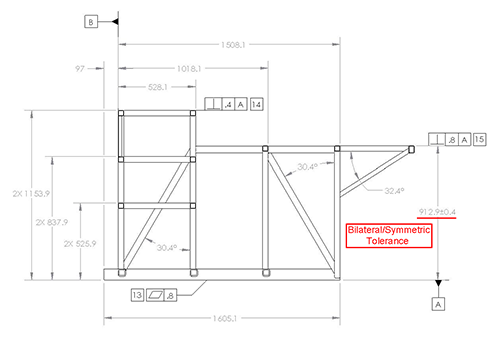
‹•› Bilateral Tolerance: A tolerance that allows the dimension to vary in both the plus and minus directions (Ex: 1.00 +.01/-.015 is a bilateral tolerance). Bilateral tolerance provides an equal allowable variation, larger and smaller.
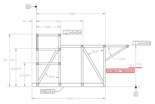
‹•› Unilateral Tolerance: Where allowable variation is only in one direction and zero in the other (Ex: .500 +.004/-.000 in a unilateral tolerance).
‹•› Plus and Minus Tolerance: The nominal or target value of the dimension is given first, followed by a ± expression of tolerance (Ex: .250±.005 is a plus-minus tolerance).
Basic Tolerance: In Geometric dimensioning and tolerancing, basic dimensions are defined as a numerical value used to describe the theoretically exact size, profile, orientation or location of a feature or datum target. Basic dimensions are currently denoted by enclosing the number of the dimension in a rectangle.
How much tolerance is a basic dimension allowed? If a basic dimension does not show a specific tolerance what tolerance should be applied? Basic dimensions by nature are a theoretically exact value; however, the feature(s) of a part they define as ideal or exact do need to have tolerances to permit acceptable levels of imperfection during manufacturing.
Coordinate Tolerancing: CT is a dimensioning system where a part feature is located by a means of rectangular dimensions with given tolerances. CT or coordinate tolerancing, does not have the completeness needed today to enable efficient and economical production of parts.
Square or rectangular tolerance zones.
Fixed size tolerance zones.
Ambiguous instructions for inspection.
Good Used of Coordinate Dimensioning: Size, Chamfer, and Radius.
Poor Used of Coordinate Dimensioning: Locating Part Features, Controlling Angular Relationships, Defining the Form of Part Features.
FEATURE OF SIZE AND DIMENSION
Feature is a general term applied to a physical portion of a part such as a surface, hole or slot.
Feature of Size: FOS refers to any surface, or set of parallel surfaces associated with a size dimension. Ex: A hole diameter (a cylindrical surface), a plate thickness (two opposed parallel surface).
Internal Feature of Size: Comprised of a part surfaces, or elements, that are internal part surfaces such as hole diameter or the width of a slot
External Feature of Size: Comprised of a part surfaces, or elements that are external surfaces such as a shaft diameter or an overall width or height of a planar part
Feature of Size Dimensions: A feature of size dimension is a dimension that is associated with a feature of size.
Non-Feature of Size: Non-FOS is a dimension not associated with a feature of size.


