|
|
AUTOCAD DRAWING SET UP
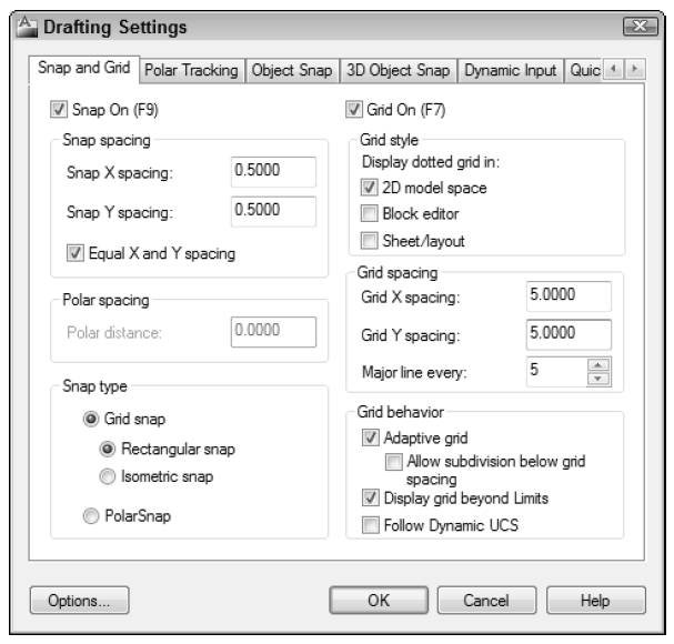
Setting up a Simple Drawing: To make it easier to plot a drawing from model space —» File —» New —» select acad.dwt (acad) or acadiso.dwt or caddlt.dwt —» Open —» type LIMITS (define your working area) —» Enter —» <0.0000,0.0000> (lower left corner) —» Enter —» 15,10 (B-size drawing working area) —» Enter —» right-click Grid On/Off icon (left bottom tool bar) —»  Grid Setting —» Drafting Settings —» change the values in the dialog box so it looks like this —» OK —» Ctrl + S (to save) —» save it to a folder (.dwg is automatically add).
Drawing Setup: The difficult aspects of using AutoCad. Quick setup really becomes apparent at plotting (printing). Decisions to make about the new drawing: What system of measurement – Metric / Imperial —» What drawing units will be use? —» At what scale – or scales – will you print it? —» What size paper does it need to fit?
Or find an existing drawing that was set up for the drawing scale and paper size, make a copy of that DWG file, erase the objects, and start drawing. With this approach, any setup mistakes in that drawing will be inherited.
Setup a white background: Tools —» Options —» select Display tab —» Windows Elements group —» select Colors button —» Drawing Window Colors dialog box —» in Context settings —» select 3D parallel projection —» in Interface elements settings —» select Uniform background —» in Color drop-down list—» select white —» in Interface element settings —» select Grid Major Lines —» in Color drop-down list —» click Select Color... —» in Color dialog box —» select Index Color tab —» in the color box —» enter 253 —» OK —» in Interface element settings —» select Grid Minor Lines —» in Color drop-down list —» click Select Color... —» in Color dialog box —» select Index Color tab —» in the color box —» enter 254 —» OK —» Apply & Close —» Apply & OK.
SPONSORED CONTENT

Flat Rolled Stainless Steel

Flat Rolled Carbon Steel

Your Metal Supermarkets

Vietnam Sheet-Metal Supplier
Scott Stainless Steel, Inc. A reliable wholesaler, distributor and service center for stainless steel based out in Northbrook, Illinois. Stainless steel strip coil and wide coil is our primary products with outstanding service, price and quality. ISO 9001 Certified.
Harvard Steel specializes in providing a broad inventory of carbon sheet products. Hot Rolled | Cold Rolled | Galvanized | Galvannealed | Electro-Galvanized | Alumnized. Between the depth of our inventory and diverse product availability, you are assured to have what you need, when you need it.
Metal Supermarkets is a provider of small quantity metals, cut to the customer's desired size, with no minimum order quantities. The world's largest small-quantity metal supplier over 100 brick-and-mortar stores across the Canada and the United States.
ITEQ Vietnam Co., Ltd is the best partner to outsource sheet metal production in Asia. ITEQ VietNam is a manufacturing company that provides both industrial and product engineering services. We primarily specialise in laser cutting, producing high quality welding, stud welding, rolling and finishing.
Choosing the Units: System of measure includes —» Format —» Unit —»
‹•› Length units: To measure linear objects and distances. The Length unit types are: —»
- Architectural units are based in feet and inches and use fractions to represent partial inches.
- Decimal units are unitless — that is, they are not based on any particular real-world unit. With decimal units, each unit in the drawing could represent an inch, a millimeter, a cubit, or any other unit of measure.
- Engineering units are based in feet and inches and use decimals to represent partial inches.

- Fractional units, like decimal units, are unitless and show values as fractions rather than decimal numbers.
- Scientific units are also unitless and show values as exponents, used for drawing really tiny or really large things. Scientific and Micro-Product design such as organic light-emitting diode or organism.
‹•› Angle units: To measure angles between nonparallel objects or points on arcs or circles. The Angle unit types are: —»
- Decimal Degrees show angles as decimal numbers and are by far the easiest to work with.
- Deg / Min / Sec is based on the old style of dividing a degree into minutes and minutes into seconds.
- Grads and Radians are mathematically usefull but are not widely used in drafting.
- Surveyor's Units type is similar to Deg / Min / Sec, but uses quater circles (quadrants), rather than a whole circle, where an angle in Deg / Min / Sec might measure 300°0'0.00", the same angle in Surveyor's Units would be represented as S 30°0'0.00" E.
—» Direction (tab) to control base angle direction. The most unit types used are Decimal, Architectural, and Decimal Degree.
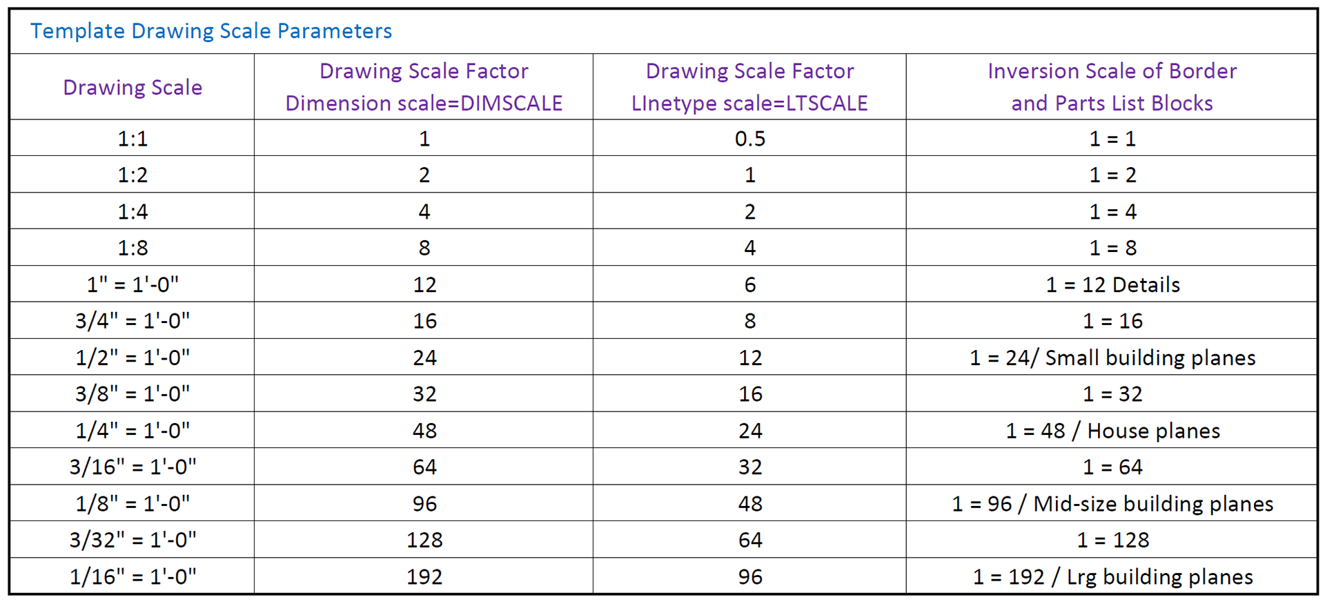
Drawing Scale v.s. Drawing Scale Factor: Drawing scale is the traditional way of describing a scale. Drawing scales are expressed with an equal sign or colon; for example, 1/8" (paper measurement) = (corresponds to) 1'-0" (real-world measurement). In other worlds, the imperial drawing scale 1/8" = 1'-0" means that 1/8" on the plotted drawing corresponds to 1'-0" in the CAD drawing and in the real-world. A metric drawing scale is usually expressed without units, as a simple ratio, 1:20 means 1 unnit on the plotted drawing corresponds to 20 units in the real-world. In architectural and engineering drawings, the numbers usually refer to millimeters. Drawing scale factor is a single number that represents a multiplier, such as 96, 20, or 0.5. The drawing scale factor for a drawing is the conversion factor between a measurement on the plot and a measurement in the real world. Choose a drawing scale —» setup drawing scale factor.
Drawing Sheet Sizes: Most industries use a small range of standard sheet sizes. Three commons sets of sizes are:
‹•› ANSI (American National Standards Institute): A (8 1/2 x 11") — B (11 x 17") — C (17 x 22") — D (22 x 34") — E (34 x 44").
‹•› Architectural: A (9 x 12") — B (11 x 17") — C C (12 x 18") — D (18 x 24") — E (24 x 36") — Large E (36 x 48").
‹•› ISO (International Organization for Standadization): A4 (210 x 297) — A3 (297 x 320) — A2 (420 x 594 mm) — A1 (594 x 841) — ISO A0 (841 x 1189 mm).
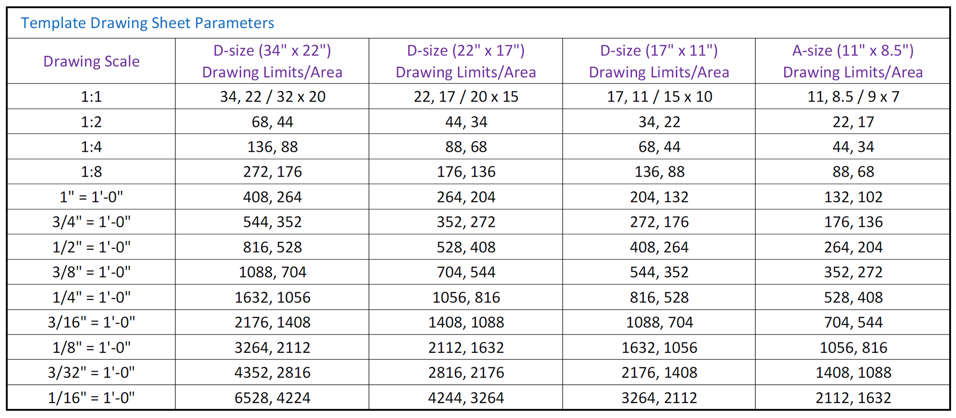
Drawing Area: After select a sheet size and drawing scale factor, calculating the available drawing area is easy. Multiply sheet's dimensions by the drawing scale factor of 96 (drawing scale factor). Ex: 1/8" = 1'0" — 17 x 96 = 1,632" and 11 x 96 = 1,056" or 136' x 88'. Two reasons why drawing area needed...
- Margin allowance: Plotters and printers can't print to the edge of the sheet.
- Annotations: Drawings require some annotations — text, dimensions. grid bubles, and so on — outside the drawing objects plus a title block surrounding the objects and annotations.
To prepare your drawing for printing (8 1/2" x 11"/210 mm x 297 mm), switch to paper space. Here you can set up different layouts with title blocks and notes; and on each layout, you create layout viewports that display different views of model space. In the layout viewports, you scale the model space views relative to paper space. One unit in paper space represents the actual distance on a sheet of paper, either in millimeters or inches, depending on how you configure your page setup.
DRAWING SHEET SIZES & SETTINGS
SPONSORED CONTENT

Your Service Flyer

Your Event Invitation

Your Promotion Ads

Your Logo & Brand
Support us and grow your business with us. My goal was to make technical information available with ready access to commonly needed resources, formulas, and reference materials while performing my work as a Technical Support Engineer. The businesses listed in the Sponsored Content section were randomly selected because of their uniqueness. However, non-sponsored selected ads will be rotated monthly.
Viba Direct lacks an advisory board to do research and hire writers with the latest technological knowledge. Creating an effective advisory board requires more than an invitation. Without your sponsorship, this is not possible. If your company is interested in placing the company's logo, brand, event invitation, and other promotional banners and flyers here or on any other pages. Please Customer Service for more detail.
SETTING UP TEXT STYLES
In AutoCad, a text style consists of a combination of a style name, a text font, a height, a width factor, an oblique angle, and a few other mostly static settings.
Determining the Text and Drawing Scales: When the text you're adding does not specifically label the portion of your design drawn at full size, 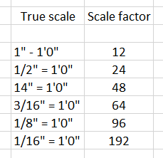 a feature called layouts makes if possible to set the height of text in the same way at which it will be printed.
A scale of 1/4" = 1'0" (1:50) has a true ration of 1:48 (1:50) and a scale factor of 48 (50), see table Standard scales and their corresponding ratios.
Defining a Text Style for View Titles: Create a new layer name A-ANNO-TEXT (yellow color and make it current) —»
‹•› Home —» Annotation panel —» select Text Style button (or enter ST¬ to start the STYLE command —» select Manage Text Styles —» New —» Style Name=A-Title (used for Headings & Titles) —» OK —» select A-Title (to edit) —» Font (Font Name=Arial) AutoCad can use both its native SHX (compiled shape) and Window TTF (TrueType font) files —» Font Style=Bold —» Height=.24 (6.0) —» Apply —» Set Current —» Close —» Save As acad-landscape.dwt (same location) —» Save.
CREATING a BORDER and TITLE BLOCK
Because 11" x 17" (297 mm x 420 mm) format drawing is legible, we'll use that sheet size. How big an area will fit on an 11" x 17" (A3, or 297 mm x 420 mm) sheet at 1/4" = 1'0" (1:50) scale. The answer is quite simple. Every inch (millimeter) on the sheet represents 48" (50 mm) in the drawing (because 12" divided by 1/4" is 48", and 50 mm divided by 1 is 50 mm). Therefore, you multiply each dimension of the sheet in inches (millimeters) by 48 (50). For this sheet, you multiply 11" x 48" (297 mm x 50) to get 528" (14,850 m m) or 45'4". You multiply 17" x 48 (420 mm x 50) to get 816" (21,000 mm), or 68' (21 meters). So the sheet repreents a rectangle with dimensions of approximately 528" x 816" (14,850 mm x 21,000 mm) at a scale of 1/4" = 1'0", which is usually called quarter-inch scale.
Most printers and plotters are not full-bleed devices, you'll need to factor in room for a margin around the outer edge of the sheet.
Drawing the Border: The border of the drawing will be set in from the edge of the sheet. Open acad-lamdscape.dwt —» Create a new layer name A-ANNO-TTLB (green color and make it current) —» Layer Properties —» RMB —» New Layer (Name=A-ANNO-TTLB) —» Color=Green —» RMB —» Set current —» Close —»
‹•› Rectangle —» 0,0¬ —» 12, 9¬ (305, 228) —» to move the rectangle, click the rectangle to select —» click the lower left grip —» press the space bar to switch from Stretch mode to Move mode —»
‹•› Offset the rectangle .5" (12 mm) to the inside —» Offset —» .5¬ —» select the rectangle —» click the inside rectangle to offset —»the outer rectangle represents the dge of the sheet of paper, and the thicker, inner rectangle is the drawing border.
Title Block: The most efficient way of creating a title block is as a separate DWG file, drawn at its normal plotted size (for example, 17 inches long by 11 inches high for a B-size title block, or 841 mm long by 594 mm high for an ISO A1-size. Then insert or xref the title block drawing into each sheet drawing.
Constructing a Title Block: We'll use the RECTANG and PLINE commands to draw the various lines that make up the title block, and then we'll fill in the text. Open acad-lamdscape.dwt —»
‹•› Rectangle —» 11.5,.50¬ —» -6, 2¬ (292, 12.7) —» Draw the title block —»
Putting Text in the Title Block: The title block has several boxes that will each contain different pieces of information and more, depending on the complexity of the job —»
‹•› Create a new layer name A-ANNO-TTLB-TEXT (cyan color and make it current) —» Manage Text Style —» create a new layer name A-ANNO-TTLB (green color and make it current) —» New (A-Ttlb) —» OK —» change A-Ttlb text height to .15 —» deselect the Annotative check box —» Apply —» set current —» Close —»
‹•› Cap Lock's on —» Single Line Text (type in information) —» J¬ (Justify) —» TL¬ (top-left) —» to be continues...
LAYOUT WIZARD — CREATING A NEW LAYOUT
Paper Space: Paper space is a sheet layout environment where you can specify the size of your sheet, add a title block, display multiple views of your model, and create dimensions and notes for your drawing. You can use multiple layouts to show and provide details on the various components of your model. You can vary the scale of the model view to show small details which are part of a bigger three-dimensional model, on standard-sized drawing sheets.
Model space: Aaccessible from the Model tab and paper space is accessible from the layout tabs. The two spaces are accessible near the left bottom corner of the drawing area: the Model tab and Layout1 and Layout2 tabs. You can add new layouts or copy existing layouts. You can create layouts using the Create Layout wizard or DesignCenter. Each layout can contain different page setup settings. To avoid confusion when transmitting and publishing drawings, it is usually recommended that you create only one named layout for each drawing.
On each layout, you can create as many layout viewports as you like. Each layout viewport is like a picture frame into model space, containing a view that displays the model at the scale and orientation that you specify. You can create a single layout viewport that fits the entire layout or create multiple layout viewports. Once you create a viewport, you can change its size, properties, and also scale and move it as needed. You can also specify which layers are visible in each layout viewport.
NỘI DUNG TÀI TRỢ

Quảng Cáo Dịch Vụ

Quảng Cáo Sự Kiện

Quảng Cáo Khuyến Mãi

Biểu Trưng & Nhãn hiệu
Hỗ trợ chúng tôi và phát triển doanh nghiệp của bạn với chúng tôi. Mục tiêu của tôi là cung cấp thông tin kỹ thuật với khả năng truy cập sẵn sàng vào các tài nguyên, công thức và tài liệu tham khảo thường cần thiết trong khi thực hiện công việc của mình với tư cách là Kỹ sư hỗ trợ kỹ thuật. Các doanh nghiệp được liệt kê trong Nội dung được Tài trợ đã được lựa chọn cẩn thận vì tính độc đáo của chúng. Tuy nhiên, các quảng cáo liệt kê không được tài trợ sẽ được luân chuyển thay đổi hàng tháng.
ViBa Direct thiếu một ban cố vấn để thực hiện nghiên cứu và thuê các nhà văn với kiến thức kỹ thuật hiện đại. Việc tạo ra một ban cố vấn hiệu quả đòi hỏi nhiều hơn là một lời mời. Nếu không có sự tài trợ của bạn, điều này khó có thể thực hiện. Nếu công ty của bạn có nhu cầu quảng cáo, đặt biểu trưng, thương hiệu, biểu ngữ mời tham gia thảnh viên, hội viên cũng như các bích chương quảng cáo ở đây hoặc trên bất kỳ trang nào khác, xin vui lòng liên hệ Dịch Vụ Khách Hàng Dịch Vụ Khách Hàng để biết thêm chi tiết.
Template: A template is simply a drawing whose name ends in the letters DWT, which you use as the starting point for another drawing. When you create a new drawing from a template, AutoCAD makes a copy of the template file and opens the copy in a new drawing editor window. The first time you save the file, you’re prompted for a new filename to save to; the original template file stays unchanged. When you create a layout, you can choose to apply the information from an existing template. A layout template is a layout imported from a DWG or DWT file. AutoCad has sample layout templates acadiso.dwt (for metric system) , acad.dwt (imperial system) to use when you design a new layout environment. AutoCad templates are probably not setup for the scales to your design which you will need to specify scale-dependent setup information.
1. Creating Drawing from a Template: Ctrl + N or QNEW (New) —» select acad.dwt —» Open —» units (see below) —» Save —» select Layout1 —» switch to PaperSpace —» select the vewport and delete it —» OP (options) —» Display tab de-select Create viewport in new layouts —» RMC on Layout1 tab —» select Page Setup Manager —» New —» New page setup name, type Electrical D —» OK —» Name select DWF6ePlot.pc3 —» Paper Size select ARCH D (36.0 x 24.0 Inches) —» Plot area, select Layout —» Plot style table, select monochrome.ctb —» select Display plot styles —» scale = 1:1 —» Plot options: select Plot project lineweights + Plot with plot styles + Plot paperspace last —» OK to create —» DL on Electrical D —» Close.
‹•› Units Settings: UN —» Type select Decimal / Precision = 0.000 —» Angle = Decimal Degrees / Precision = 0 / Uncheck Clockwise (angles measures counter-clockwise and use east as the 0 degree direction)—» Insertion scale = Inches —» Lighting = International —» OK —» select Model tab —» select Rectangle tool to draw a rectangular @34x22 (D size) —»
Limits Settings: LIMITS —» Enter —» by default, the lower-left corner of the screen is 0,0 —» Enter —» specify upper right corner (see Template Drawing Sheet Parameters Table below) —» Enter.
Grid Settings: GRID OR F7 —» the tool bar below —»
‹•› M (Major): Specifies the frequency of major grid lines compared to minor grid lines. Grid lines rather than grid dots are displayed.
‹•› D (Adaptive): Controls the density of grid lines when zoomed in or out. This setting is also controlled by the GRIDDISPLAY system variable.
‹•› L (Limits): Displays the grid beyond the area specified by the LIMITS command.
‹•› F (Follow): Changes the grid plane to follow the XY plane of the dynamic UCS. This setting is also controlled by the GRIDDISPLAY system variable. 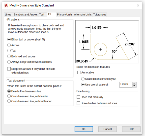
‹•› A (Aspect): Changes the grid spacing in the X and Y directions, which can have different values. Not available when the current snap style is Isometric.
Snap Settings: Tools —» Drafting Settings —» Object Snap —» F3 = Osnap On/Off —» to choose an object snap from the Object Snap toolbar —» press Shift + Right-click —» select/deselect a snap feature. See toolbar shortcut A and B.
Linetype Scale Settings: Linetype is a visual property assigned to geometric objects. Linetypes can be a pattern of dashes, dots, text, and symbols, or unbroken and continuous. Before you can use different linetypes, you must load them in the drawing with the Linetype Manager. Linetype scale controls the size and spacing of repetitions of the linetype pattern for each drawing unit. There are a number of scaling options that can affect how linetypes display and plot. LTS (LTSCALE) —» Enter —» type the value —» Enter. The simple choice is to set the linetype scale to the drawing scale factor.
Dimension Scale: To set the overall dimension scale —» Dimension —» Dimension Style —» select a style to change —» Modify —» Fit (tab) —» under Scale for dimension features —» Use overal scale of —» enter a value —» OK. Shortcut to dimension scale is DIMSCALE.
Choose a drawing scale and sheet size to set up the drawing. Most drawings require a two-part setup: 1. Setup model space to model your part. 2. Create one or more paper space layouts for plotting.
2. Create a Title Block (D size): LA (layer) —» New Layer —» rename as A-Border and make it current —» select Lineweight and select 0.70 mm —» OK —» X to close the Layer window —» Home and select Rectangle tool to draw —»  select the top left corner of the paper + hold and drag to the bottom right corner of the paper (or type in 36,24) —» click to place or enter if typed in —» type O (offset) —» .75 is offset distance —» Enter —» click the border and then click inside —» Enter —» select the outside rectangle and delete and verify that the created border is inside the dotted rectangular all around. If not, center the created border —» X (explode) —» select the Border and RMC to explode —» O (offset) —» type 1 and Enter —» select the right border —» RMC to offset —» repeat offset and type 2.75 —» select the right border and offset 1.75. Ideally is offseting from bottom and right border to finish the Title Block layout (see image above).
Create new layers named A-Text and A-Viewport —» double click A-Text to make this layer current and turn off A-Viewport layer —» Save As —» Files of type select AutoCAD Drawing Template (.*dwt) —» select the company template folder to save in —» File name, type Electrical D —» Save —» Description, type Electrical Drawing Template —» select save all Layers and unreconciled —» OK —»
Create a Viewport: Select Layout1 tab —» LA to turn on Viewport layer and make it current —» MV (MVIEW) to create a viewport —» OSNAP (Off) —» select the left top corner of the drawing hold and drag to the bottom right of the drawing to create a viewport —» click to create —» select ModelSpace —» select scale the selected viewport 1:1 —» lock the viewport.
When you create a new layout template, any named items, such as blocks, layers, and dimension styles, that are used in the layout are saved with the template. These definition table items are imported as part of the layout settings if you import this template into a new layout. It is recommended that you use the Save As option of the LAYOUT command to create a new layout template. When you use the Save As option, unused definition table items are not saved with the file; they are not added to the new layout into which you import the template.
If you insert a layout from a drawing or template that was not created using the Save As option of the LAYOUT command, definition table items that are used in the drawing but not in the layout are inserted with the layout. To eliminate unnecessary definition table items, use the PURGE command.
To Save a Layout Template: Open a Drawing File —» Save As (Ctrl+Shift+S) —» File name=Levels Control MMC as a drawing file (.dwg) —» Save As (Ctrl+Shift+S) —» Files of type: select Drawing Template File (*.dwt) —» File name=A-Hor-Metric —» Save —» Description=A size-Horizontal-Metric —» Measurement=select Metric —» New Layer Notification=Save all layers as unreconciled —» OK.
Your Support Can Help Us Grow. Thank you for visiting ViBa Direct. As part of our commitment to continually improving the visitor experience, we’re doing our best to add the latest information with ready access to commonly needed resources, engineering, formulas, reference materials, photography, and travel. Unfortunately, we don't have enough manpower to meet everyone's needs. But if you are interested in helping us with the site maintenance cost. Please mail your donation to ViBa Direct., P.O. Box 1801., Pflugerville, TX 78691. Thank you for taking the time to read this. Feel free to Customer Service with any additional feedback you would like to share about your experience visiting ViBaDirect.com


