MATERIAL CONDITION (Level 1, 2, 3 & 4 Control)
Material condition is another way of thinking about the size of an object taking into account the object's nature. For example, the nature of a mountain is that it's a pile of rock material. If you pile on more material, its "material condition" increases and the mountain gets bigger. The nature of a canyon is that it's a void (trống, bỏ không, trống rỗng, khuyết). As erosion decreases its "material condition," the canyon (hẽm núi) gets bigger.
If a mating feature of size is as small as it can be, will it fit tighter or sloppier? Of course, you can't answer until you know whether we're talking about an internal feature of size, such as a hole, or an external feature of size, such as a pin. But if we tell you a feature of size has less material, you know it will fit more loosely regardless of its type. Material condition, then, is simply a shorthand description of a feature's size in the context of its intended function.
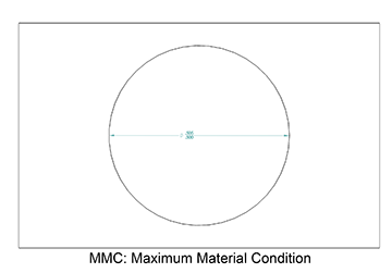
Maximum material condition (MMC) is the condition in which a feature of size contains the maximum (tối đa) amount of material within the stated (trạng thái; tình trạng) limits of size. For a shaft and hole base system, a shaft will be in MMC when it has the maximum diameter and a hole will be in MMC when it has minimum diameter. (e.g., minimum hole diameter, maximum shaft diameter). In the above figure the size of the hole can vary from 505 to .500. And at .500 it will be in MMC. You can think of MMC as the condition where the most part material is present at the surface of a feature, or where the part weighs the most (all else being equal). This equates (tương đương với) to the smallest allowable hole or the largest allowable pin, relative to the stated size limits.
Least material condition (LMC) is the condition in which a feature of size contains the least (tối thiểu) amount of material within the stated limits of size (e.g., maximum hole diameter, minimum shaft diameter). You can think of LMC as the condition where the least part material is present at the surface of a feature, or where the part weighs the least (all else being equal). This equates to the largest allowable hole or the smallest
For every feature of size, one of the size limit boundaries is an MMC boundary (ranh giới) corresponding (tương ứng; đúng với) to an MMC limit, and the other is an LMC boundary corresponding to an LMC limit. Depending on the type of feature and its function, the MMC boundary might ensure matability or removal of enough stock in a manufacturing process; the LMC boundary may ensure structural integrity and strength or ensure that the feature has enough stock for removal in a subsequent (tiếp theo, sau) manufacturing process.
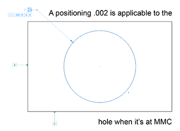
Bonus Tolerance: Bonus tolerance is the additional tolerance available for a geometric control attached to a feature of size with MMC (maximum material condition) and LMC (least material condition) modifier. Bonus tolerance is very important for mechanical design, especially where designed parts fit together such as a shaft and its mating component. In the right figure a positioning tolerance of .002 is applicable to the hole when it's at the maximum material condition (MMC). The hole diameter MMC is .500 and at this condition the inspecting gauge diameter should be .498 and holes that allow the ø.498 gauge to enter should pass the quality checks.
Since the hole diameter can vary from ø.500 to ø.505, and as the hole size increase the tolerance available between the gauge and the hole also increases.
‹•› At MMC the maximum available tolerance will be equal to .505 – .498 (gauge ø) = .007. Out of which specified positional tolerance is .002 so the bonus tolerance will be .007 – .002 = .005.
Bonus tolerance will be available for the geometric dimensioning and tolerancing feature of size with MMC or LMC modifiers. The bonus tolerance reduces the number of rejected parts by increasing the tolerance zone.
GD&T MODIFIER SYMBOLS
Each geometric tolerance for a feature of size applies in one of the following three contexts:
Regardless of Feature of Size (RFS), default • Modified to Maximum Material Condition (MMC) • Modified to Least Material Condition (LMC).
Table Geometric Characteristics and Their Attributes show which types of tolerances may be optionally "modified" to MMC or LMC. Such modification cause a tolerance to establish a new and useful fixex-size boundary based on the geometric tolerance and the corresponding size limit boundary.
Placing a material condition modifier symbol, either a circled M or a circled L, immediately following the tolerance value in the feature control frame modifies a tolerance. In notes outside a feature control frame, use the abbreviation "MMC" or "LMC". Symbol may also appear following the datum reference letter for each datum feature of size. A geometric tolerance applied to a feature of size with no modifying symbol applies RFS. A few types of tolerances can only apply in an RFS context.
APPLICABILITY OF MODIFIERS ON GEOMETRIC TOLERANCE VALUES & DATUM FEATURE REFERENCES
RFS, MMC, and LMC may be applied to geometric tolerance values on feature of size. See Im. 1-11 and 1-12.  RMB, MMB, and LMB may be applied to datum feature references. Rule #2 RFS applies, with respect to the individual tolerance, and RMB applies, with respect to the individual datum feature reference, where no modifying symbol is specified. MMC, LMC, MMB,or LMB shall be specified on the drawing where it is required.
Positional Tolerance at MMC: A positional tolerance applied at MMC may be explained in terms of the surface or the axis of the feature of size. In certain cases of extreme form deviation (within limits of size) or orientation deviation of the hole, the tolerance in terms of the axis may not be exactly equivalent to the tolerance in terms of the surface. See Im_1-13. In such cases, the surface interpretation shall take precedence. In some instances, the additional tolerance may indirectly benefit features other than the one that departed from MMC.
‹•› Surface Interpretation: While maintaining the specified size limits of the feature, no element of the surface shall violate a theoretical boundary (virtual condition) located at true position. See Im_1-14.
‹•› Axis or Center Plane Interpretation: Where a feature of size is at MMC, its axis or center plane must fall within a tolerance zone located at true position. The size of this zone is equal to the positional tolerance. See Im_1-15, illustrations (1) and (2). This tolerance zone also defines the limits of variation in the orientation of the axis or center plane of the feature of size in relation to the datum surface. See Im_1-15, illustration (3). It is only where the feature of size is at MMC that the specified tolerance zone applies. Where the unrelated actual mating envelope size of the feature of size departs from MMC, additional positional tolerance results. See im_1-16. This increase of positional tolerance is equal to the difference between the specified maximum material condition limit of size (MMC) and the unrelated actual mating envelope size. Where the unrelated actual mating envelope size has departed from MMC, the specified positional tolerance for a feature of size may be larger than the stated value and still satisfy function and interchangeability requirements.


