|
|
FORM CONTROL – STRAIGHTNESS — ASME Y14.5-2009
 There are four form controls (điều chỉnh hình thể). Flatness (mặt phẳng), Straightness (thẳng, không cong), Circularity (hình vòng tròn; dáng tròn), Cylindricity (hình trụ, cylindricity is a 3-Dimensional tolerance that controls the overall form of a cylindrical feature to ensure that it is round enough and straight enough along its axis). Practically form controls are the least used GD&T controls as other tolerances like location and orientation will have sufficient control to satisfy parts functional requirements and form.
Form Controls Never Need a Datum Reference: As a general rule, apply a form (only) tolerance to a non-datum (số lượng đã cho; điều đã cho biết luận cứ) feature only where there is some risk that the surface will be manufactured with form deviation (độ lệch) severe enough to cause problem in subsequent manufacturing operations, inspection, assembly, or function of the part.
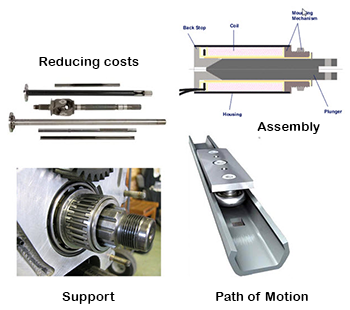
Applications used straightness tolerance: Support, Path of Motion, Assembly and Reducing cost. One real-world application for a straightness tolerance is to protect the function of assembly but not to protect the function of balance, and to mate cylindrical features of size.
Straightness Control: A geometric tolerance that, when directed to a surface, limits the amount of straightness error allowed in each surface line element. A straightness control is applied in the view where the elements to be controlled are represented by a straight line.
Straightness of a Line Element: The condition where each line elements (or axis or center plane) is a straight line.
Rule #1: Effects on Straightness Deviation: When a straightness tolerance is applied to surface elements of a cylinder, typical form deviations (sự trệch, sự lệch) for the line elements are random, bending, waisting, and barreling. Rule #1 requires the line elements (yếu tố đường kẻ) and the derived median (lấy được từ điểm giữa, trung tuyến được hình thành) line of a feature of size to have zero straightness deviation (độ lệch) at MMC. 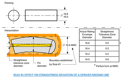 A straightness tolerance at RFS applied to a regular feature of size overrides Rule #1.
Rule #1 effect on straightness deviation of a derived median line. How much straightness deviation is permitted for the derived median line of a pin with Dia 1.003/1.000
‹•› Actual Mating Envelope (hình bao giao phối có thật) Dia: 1.003 — Straightness Tolerance Zone Diameter is .0
‹•› Actual Mating Envelope Dia: 1.002 — Straightness Tolerance Zone Diameter is .001
‹•› Actual Mating Envelope Diameter: 1.001 — Straightness Tolerance Zone Diameter is .002
‹•› Actual Mating Envelope Dia: 1.000 — Straightness Tolerance Zone Diameter is .003
Derived Median Line is an imperfect line formed by all center points of all cross sections of the feature. Derived median line (đường tìm thấy/xuất phát từ từ điểm giữa, trung tuyến được hình thành) is the term for an imperfect line formed by the center points of all cross sections of a feature of size.
In straightness of a derived median line (đường, tuyến được hình thành từ điểm giữa, trung tuyến), the tolerance zone begins as cylindrical in shape and runs through the feature’s center. The controlled feature’s derived median line must line within this tolerance zone. This derived (được hình thành) median line, which is generated by controlled feature’s surface, may bend or distort (bóp méo, làm méo mó) from a perfectly straight counterpart (vật giống hệt vật khác), but must never violate this cylindrical tolerance zone (when the MMC material condition symbol is stated, this tolerance zone may grow).
The tolerance zone for straightness of any one surface is infinite. Each line element of the surface must, independent of all other line elements, line within its own tolerance zone, which consists of two parallel lines.
STRAIGHTNESS TOLERANCE NEVER NEED A DATUM REFERENCE
Straightness Tolerance for a Cylindrical Feature: 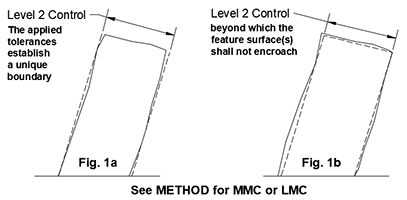 A traightness tolerance feature control frame placed according to options (a) or (d) in Table Geometric Characteristics and Their Attributes (associated with a diameter dimension) replace rule #1's requirement for a perfect form at MMC with a separate tolerance controlling the overall straightness of the cylindrical feature. Where the tolerance is modified to MMC or LMC, it establishes a Level 2 virtual condition boundary as described (Level 2 – Overall Feature Form) and in Figure 1a and Figure 1b. Alternatively, "the center method" described in (Level 2 Adjustment – Actual Local Sizes) may be applied to a straightness tolerance at MMC or LMC, but there's rarely any benefit to offset the added complexity. Unmodified, the tolerance applies RFS and establishs a central tolerance zone as described in (Tolerance Zone Shape), within which the feature's derived median line shall be contained.
The Tolerance Zones for a Straightness Tolerance:
‹•› A straightness tolerance must not be applied to surface line elements (yếu tố tuyến bề mặt).
‹•› A straightness tolerance never uses a datum reference.
A straightness tolerance maybe applied to cylindrical features of size. 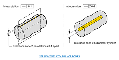
How much straightness variation is permitted for the derived median line (đường, tuyến được hình thành từ điểm giữa, trung tuyến)? How much straightness deviation is permitted for the derived median line of 12.2 – 12.7 diameter? See figure. (0.5)
What is the requirement of the straightness tolerance shown in figure? Each individual line elements must fit between two parallel lines 0.02mm apart. (Dia 12.7/12.5)
Straightness Tolerance Applied to Line Elements of a Cylincrical Surface not the Axis:
MODIFIERS THAT MAY BE USED WITH A STRAIGHTNESS TOLERANCE
Determine if a straightness tolerance is applied to line elements or to a feature of size. What is the requirement of the straightness tolerance in fig? Each individual line elements must fit between two parallel lines 0.02mm apart.
Interpret the straightness tolerance applied to line elements of a cylindrical surface. Two parallel lines is the shape of the tolerance zone for a straightness tolerance applied to surface elements of a cylindrical feature of size.
Three Requirements of a Straightness Tolerance application: The Size – Rule #1 Boundary – Straightness
STRAIGHTNESS TOLERANCE (at MMC) APPLIED TO A FOS
Straightness Tolerance (at MMC) applied to a Feature of Size Dimension: The tolerance zone is a virtual condition (acceptance boundary) — A bonus tolerance is permitted — Rule #1 don't applied.
‹•› Example: A pin with a diameter 18 mm +0.2/-0.0 and a straightness Dia 0.4 at M. What is the requirement of the straightness tolerance an 18.6 diameter virtual condition boundary that the pin surface must fit within? — The Straightness Tolerance would be zero.
VERIFICATION PRINCIPLES FOR STRAIGHTNESS TOLERANCES
Straightness Verification Principles: The inspection method for a straightness tolerance applied to line elements must be able to collect a set of points and determine the minimum distance between two lines that contains the set of points.
‹•› When a straightness tolerance contains the MMC, the best tool for verifying the straightness is a functional gage. 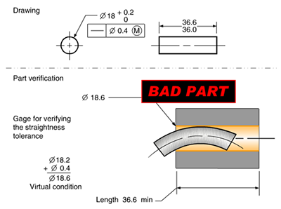
‹•› When verifying/inspecting a straightness tolerance applied to a surface, the distance from the high points to the low point of the line element must be less than the straightness tolerance value derived.
Verify a straightness tolerance applies to the elements of a cylindrical surface, each line element must be within two parallel lines (straightness tolerance specified on drawing) apart.
‹•› When inspecting a straightness tolerance applied to a surface, all points along the line element must fit between two parallel lines.
‹•› When inspecting a straightness tolerance at MMC applied to a pin diameter, the surface must fits within a virtual condition boundary.
‹•› Alternative is two equal height gage block stacks, then a bottom-dead-center T.I.R
‹•› Verify straightness of an Axis - RFS using two opposing indicators to track axial deviation.


