|
|
GD&T FUNDAMENTAL RULES & BENEFITS
Geometric Dimensioning and Tolerancing (GD&T) is a system for defining and communicating engineering tolerances. It uses a symbolic language on engineering drawings and computer-generated three-dimensional solid models that explicitly describes nominal (danh nghĩa) geometry and its allowable variation (sự thay đổi, sự khác nhau). There are many benefits implementing GD&T, most noticeably —» Product Reliabilty Improvement —» Errors, Re-work, Rejections and Scrap Elimination —» Easy to Identify Deviating Processes That Affect Quality and Restore Them for Maximizing Yield.
How GD&T Enable Drawings for Higher Product Quality and Lower Cost? Below are steps towards a correct and complete G D & T Drawing:
‹•› Define Part features that would serve as origin with specific directions for measurement. This step relates to Datums. Datums need to be selected based on the following criteria: Representative of Mating Features —» Reflect Functional Assembly —» Stable —» Repeatable —» Accessible. They are all important, the choice and order of Datums Selection need to be in alignment with the Quality objectives. In fact, Design For Assembly (DFA), that influences Datum Selection and Precedence (order), needs to be in alignment with Design For Quality (DFQ) objectives.
‹•› Specify Nominal (Basic) Dimensions for Location and/or Orientation of Features from Datums.
‹•› Specify Tolerance Zone Boundaries for Part Features in terms of shape and size along with specific rules for compliance. This step requires knowledge of process capability existing (with the organization or suppliers). Additionally the dimensioning schema should have the least number of dimensions between the datum reference and features that form a part of the measurable Design for Quality Objective. This is essential to identify the correct Critical To Quality (CTQ) or Key Characteristics for the part that would help in inspection and reporting. In comparison to the Plus/ Minus Tolerancing Schema, the GD&T approach ensures clarity in setup during manufacture & inspection, alignment with Quality objectives while keeping cost as a driver for change.
SPONSORED CONTENT

Your Service Flyer

Your Event Invitation

Your Promotion Ads

Your Logo & Brand
‹•› Allow Dynamic Interaction of Tolerance Zones between Features in a Part, and across parts, simulating Assembly possibilities for Maximizing Tolerances. This step differentiates GD&T from Plus / Minus Tolerances in enforcing a methodology that would help reduce cost while meeting Quality objectives. Drawing is incomplete without this step. Even companies that incorporate GD&T, fall short of this requirement, sometimes leading to an erroneous conclusion, that GD&T is expensive and its impact on quality is not significant.
‹•› Cost of Precision versus Cost of Poor Quality Analysis for Optimal Tolerances. By choosing alternate Process Capability, providing costs incurred to maintain specified tolerances and performing a risk assessment based on Risk Priority Number (RPN) of Design Failure Modes & Effects Analysis (DFMEA), a designer can arrive at optimal tolerances and provide KC’s (Key Characteristics) on drawings. This step ensures that management is provided with alternatives in terms of costs, choice of suppliers and investment in machinery and manufacturing lines to achieve desired levels of quality in an objective manner.
WHAT ARE RULES OF GD&T?
To help conform to this standard of measurement, a system for defining tolerances known as Geometric Dimensioning and Tolerancing (GD&T) was developed. Below are the rules of GD&T.
‹•› Each dimension shall have a tolerance, except for those dimensions specifically identified as reference, maximum, or stock. The tolerance may be applied directly to the dimension (or indirectly in the case of basic dimensions), indicated by a general note, or located in a suplementary block of the drawing format.
‹•› Dimensioning and tolerancing shall be complete so there is full understanding of the characteristics of each feature. Neither scaling nor assumtion of a distance or size is permitted, except as follows: Undimensioned drawing, such as loft, printed wiring, templates, and master layout prepared on stable (không có khả năng di động, không có khả năng thay đổi) material, are excluded provided the necessary control dimensions are specified.
‹•› Each necessary dimension of an end product shall be shown. No more dimension than those necessary for complete definition shall be given. The use of reference dimensions on a drawing should be minimized. Dimensions should NOT be duplicated, or the same information be given in two different ways.
‹•› Dimension shall be selected and arranged to suit the function and mating relationship of a part and shall not be subject to more than one interpretation.
‹•› The drawing should define a part without specifying manufacturing methods. Thus (theo cách đó, như vậy, như thế), only the diameter of the hole is given without indicating whether it's to be drilled, reamed, punched, or made by any other operation. However, in those instances (yếu tố cần thiết) where manufacturing, processing, quality assurance, or environmental information is essential to the deffinition of engineering requirements. It shall be specified on the drawing or in a document referenced on the drawing.
‹•› It's permissible (chấp nhận được, dùng được) to identify as nonmandatory (không có tính cách bắt buộc) certain processing dimensions that provide for finish allowance, shrink allowance, and other requirements, provided the final dimensions are given on the drawing. Nonmandatory processing dimensions shall be identified by an appropriate note, such as NONMANDATORY (MFG DATA).
‹•› Dimension should be arranged to provide required information for optimum (tốt nhất, tối ưu) readability. Dimension should be shown in true profile views and refer to visible outlines. Dimensions should be placed at finished surfaces or important center lines. Never cross dimension lines. Never cross extension lines.
‹•› Wires, cables, sheets, rods, and other materials manufactured to gage or code number shall be in parentheses following the dimension.
‹•› A 90° angle applies where center lines and line depicting features are shown on a drawing at right angles and no angle is specified/shown.
‹•› Unless otherwise specified, all dimension are applicable at 20°C (68°F). Compensation (sự đền bù, sự bồi thường) may be made for measurements made at other temperatures.
‹•› All dimensions and tolerances apply in a free state condition. This principle doesn't apply to nonrigid parts as defined below.
‹•› Unless otherwise specified, all geometric tolerances apply for full length, depth, and width of the feature.
‹•› Dimensions and tolerances apply only at the drawing level where they are specified. A dimension specified for a given feature on one level of drawing, (for example, a detail drawing) is not mandatory for that feature at any other level (for example, an assembly drawing).
GD&T AND NONRIGID PARTS
A nonrigid part is a part that can have different dimensions while restrained (kiềm chế) in assembly than while relaxed (thanh thản) in its "free state." Rubber, plastic, or thin-wall parts may be obviously nonrigid. Other parts might reveal themselves as nonrigid only after assembly or functioning forces are applied. That's why the exemption of "nonrigid parts" from Fundamental Rule is meaningless. Instead, the rule must be interpreted as applying to all parts and meaning. "Unless otherwise specified, all dimensions and tolerances apply in it free state condition." Thus, a designer must take extra care to assure that a suspected nonrigid part will have proper dimensions while assembled and functioning. To do so, one or more tolerances may be designated to apply while the part's assembly and/or functioning.
NONRIGID PARTS AND SPECIFYING RESTRAINT
Specifying Restraint: A nonrigid part might conform (thích nghi với) to all tolerances only in the free state, only in the restrained state, in both states, or in neither state. Where a part, such as a rubber grommet, may or may not need the help of restraint for conformance (sự phù hợp, sự thích hợp), the designer may specify optional restraint. This allows all samples to be inspected in their free states. Parts that pass are accepted. Those that fail may be reinspected — this time, while restrained. Where there is a risk that restraint could introduce unacceptable distortion, the designer should specify mandatory (có tính cách bắt buộc) restraint instead.
Restraint may be specified by a note such as UNLESS OTHERWISE SPECIFIED, ALL DIMENSIONS AND TOLERANCES MAY (or SHALL) APPLY IN A RESTRAINED CONDITION. Alternatively, the note may be directed only to certain dimensions with flags and modified accordingly (phù hợp với điều đã được nhắc đến hoặc biết đến). The note shall always include (or reference a document that includes) detailed instructions for restraining the part. A typical note (example: THIS TOLERANCE APPLIES WHEN DATUM FEATURE A IS MOUNTED AGAINST A FLAT SURFACE USING FOUR .250-28 BOLTS TORQUED TO 10 FOOT POUNDS.) identifies one or two functional datum features (themselves nonrigid) to be clamped into some type of gage or fixture. The note should spell out any specific clamps, fasteners, torques, and other forces deemed necessay to simulate expected assembly conditions.
GD&T RULE NUMBER 1
Rule #1 at MMC (Only): Y14.5 decrees (quy định) that, unless otherwise specified or overridden by another rule, a feature's MMC size limit spine shall be perfectly formed (straight or flat, depending on its type). Ex: A diameter .997–1.000 shaft then its MMC is 1.000. It's in perfect form that it's should have perfect straightness, circularity and cylindricity. This invokes (viện dẫn chứng) a boundary of perfect form at MMC (also called an envelope). The form tolerance increases as the actual size of the feature departs from MMC toward LMC. Rule #1 doesn't require the LMC boundary to have perfect form.
GD&T RULE NUMBER 2
Rule #2: RFS automatically applies. (ex: diameter 1.000 / .900 / .800 steeped shaft). The bigger diameter is asigned as (datum B) and the smaller diameter .800 is controlled by a concentric geometric tolerance and this tolerance is applied without any dimensional size constraints ie regardless of feature size (RFS).
LEVEL 1, SIZE LIMITS, AND SIZE LIMIT BOUNDARIES
Size Limits (Level 1 Control): For every feature of size, the designer shall specify the largest and the smallest the feature can be. 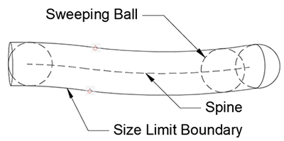 The standards provide three options for specifying size limits on the drawing: symbols for limit and fits, limit dimensioning (Ø.250/.245 or Ø.245/.250) or (25.45/25.00 not 25.45/25 or 32 +0.25/–0.10 not 32 +0.25/–0.1), and plus and minus tolerancing (.247 +.003/-.002 or .250 +/–.005) or (32 0/–.02 or 32 +0.02/0). Where tolerances directly accompany a dimension, it's important to coordinate the number of decimal places expresed for each value to prevent confusion. The rules depend on whether the dimension and tolerance values are expressed in inches (.500 +.005/–.000 not .500 +.005 /0) or millimeters (0.7 not .7 or 25.1 not 25.10 or 12 not 12.0).
Size Limit Boundaries: For every feature of size, the designer shall specify the largest and the smallest the feature can be (see Size Limits). With size limit boundary, we're concerned with the exact requirements these size limits impose (áp đặt) on a feature. It starts with a geometric element called a spine. The spine (xương sống) for a cylindrical feature is a simple (nonself-intersecting) curve in space that may be straight or wavy, and we take an imaginary solid ball whose diameter equals the small size limit of the cylindrical feature, and sweep its center along the spine. This generates a "wormlike" 3-dimensional bounday for the feature's smallest size. Then, we may create a second spine, and sweep another ball whose diameter equals the large size limit of the cylindrical feature. This generates a second 3-D boundary, this time for the feature's largest size. As shown in the right image, a cylindrical feature of size conforms to its size limits when its surface can contain the smaller boundary and be contained within the larger boundary. Under Levevel 1 control, the curvatures and relative location of each spine may be adjusted as neccdessary to achieve the hierarchy of containments, except that the small size limit boundary shall be entirely contained within the larger size limit boundary.
Whether it's an internal or external feature, both feature surfaces shall contain the smaller boundary and be contained within the larger boundary.
LEVEL 2 CONTROL OVERALL FEATURE FORM AND ACTUAL LOCAL SIZES
Level 2 – Overall Feature Form: For feature of size that must achieve a clearance fit in assembly, such as the right image (Cylindrical features of size that must fit in assembly), 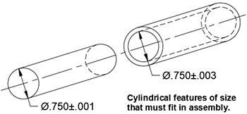 we calculate the size tolerances based on the assumption that each feature, internal and external, is straight. Ex: The designer knows that a Ø.501 maximum pin will fit in a Ø.502 minimum hole if both are straight. If one is out of shape, they usually won't go together. Because Level 1's size limit boundaries can be curved, they can't not assure assemblability. Leve 2 adds control of the overall geometric shape of form of a feature of size by establishing a perfectly formed boundary beyond which the feature's surface(s) shall not encroach (xâm lấn, xâm phạm).
‹•› Boundaries of Perfect Form: A size limit spine can be required to be perfectly formed (straight or flat, depending on its type). Then, the sweeping ball generates a boundary of perfect form, either a perfect cylinder or pair of parallel planes. The feature surface(s) must then achieve some degree of straightness or flatness to avoid violating the boundary of perfect form. Boundaries of perfect form have no bearing (liên quan, quan hệ) on the orientational, locational. or coaxial relationships between features. However, this Level 2 control is usually adequate (tương xứng, xứng đáng; thích hợp, thích đáng, thoả đáng) for a feature of size that relates to another feature in the absence of any orientation or location restraint between the two features – that is, where the features are free-floating relative to each other. Where necessary, overall form controled may be adjusted with a separate straightness, flatness, or cylindricity tolerance, described in (Straightness Tolerance for a Cylindricity Tolerance — Flatness Tolerance for a Width-Type Feature and Cylindricity Tolerance), respectively.
 For an individual feature of size, the MMC and LMC size limit boundaries can be required to have perfect form in four possible combinations: MMC only (see Rule #1), LMC only, both, or neither. Each combination is invoked by different rules which, unfortunately, are scattered throughout Y14.5.
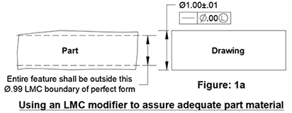
- At LMC (Only): Figure 1a illustrates a case where a geometric tolerance is necessary to assure an adequate (tương xứng, xứng đáng; thích hợp, thích đáng, thoả đáng) "skin" of part material in or on a feature of size, rather than a clearance fit. In such an application, the feature of size at LMC represents the worst case. An LMC modifier applied to the geometric tolerance overrides Rule #1 for the controlled feature of size. Instead, the feature's LMC spine shall be perfectly formed (straight or flat, depending on its type). This invokes a boundary of perfect form at LMC. The MMC boundary need not have perfect form. The same true for a datum feature of size referenced at LMC.
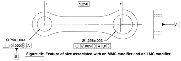
- At both MMC and LMC: There are cases where a feature of size is associated with an MMC modifier in one context, and an LMC modifier in another context. Figure 1b illustrate the datum B bore is controlled with a perpendicularity tolerance at MMC, then referenced as a datum feature at LMC. Each modifier for this feature, MMC and LMC, invokes perfect form for the feature's corresponding size limit boundary.
- At neither MMC nor LMC – the Independency Principle: Y14.5 exempts (miễn, được miễn) the follwing from Rule #1.
— Stock, such as bars, sheets, tubing, structural shapes, and other items produced to established industry or government standards that prescribe limits for straightness, flatness, and other geometric characteristics. Unless geometric tolerances are specified on the drawing of a part made from these items, standards for these items govern (ảnh hưởng) the surfaces that remain in the as-furnished condition on the part.
— Dimensions for which restrained verification is specified in accordance with (see Specifying Restraint).
— A cylindrical feature of size having a straightness tolerance associated with its diameter dimensions as described in (see Straightness Tolerance for a Cylindrical Feature).
— A width-type feature of size having a straightness or (by extension of principle) flatness tolerance associated with its width dimensions as described in (Flatness Tolerance for a Width-Type Feature).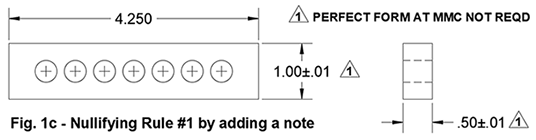
In these cases, feature form is either noncritical or controlled by a straightness or flatness tolerance separate from the size limit. Since Rule #1 doesn't apply, the size limits by themselves impose neither an MMC nor an LMC boundary of perfect form. Example of an electrical bus bar In Fig. 1c, the cross-sectional dimensions have relatively close tolerances, not because the bar fits closely inside anything, but rather because of a need to assure a minimumcurrent-carrying capacity without squandering expensive copper. Neither the MMC nor the LMC boundary need be perfectly straight. However, if the bus bar is custom rolled, sliced from a plate, or machined at all, it won't automatically be exempted from Rule #1. In such a case, Rule #1 shall be explicitly nullified by adding the note PERFECT FORM AT MMC NOT REQD adjacent to each of the bus bar's size dimensions.
‹•› Virtual Condition Boundary for Overall Form: There are cases (page 5-30)
Level 2 Adjustment – Actual Local Sizes: Since Level 3 and 4 tolerances impose (page 5-45).....developing projects.
Level 2 Tolerances: It is intended to control feature form. Thus, the tolerance zone must interact with actual feature size independently at each cross section of the feature. Though the effective control is reduced from 3D down to 2D, inspection is more complicated.
‹•› Straightness of a Cylindrical Feature at MMC. The central tolerance zone is bounded by a revolute (cuốn ngoài), within which the derived median line (đường tìm thấy/xuất phát từ từ điểm giữa, trung tuyến được hình thành) shall be contained. At each cross-sectional slice, the diameter of the tolerance zone varies according to the actual mating local size. Within any plane perpendicular to the axis of the actual mating envelope, actual mating local size is the diameter of the largest perfect circle that can be inscribed (vẽ nội tiếp) within an internal feature, or the smallest that can be circumscribed (vẽ hình ngoại tiếp) about an external feature, so that it just contacts the feature surface.
NỘI DUNG TÀI TRỢ

Quảng Cáo Dịch Vụ

Quảng Cáo Sự Kiện

Quảng Cáo Khuyến Mãi

Biểu Trưng & Nhãn hiệu
Hỗ trợ chúng tôi và phát triển doanh nghiệp của bạn với chúng tôi. Mục tiêu của tôi là cung cấp thông tin kỹ thuật với khả năng truy cập sẵn sàng vào các tài nguyên, công thức và tài liệu tham khảo thường cần thiết trong khi thực hiện công việc của mình với tư cách là Kỹ sư hỗ trợ kỹ thuật. Các doanh nghiệp được liệt kê trong Nội dung được Tài trợ đã được lựa chọn cẩn thận vì tính độc đáo của chúng. Tuy nhiên, các quảng cáo liệt kê không được tài trợ sẽ được luân chuyển thay đổi hàng tháng.
ViBa Direct thiếu một ban cố vấn để thực hiện nghiên cứu và thuê các nhà văn với kiến thức kỹ thuật hiện đại. Việc tạo ra một ban cố vấn hiệu quả đòi hỏi nhiều hơn là một lời mời. Nếu không có sự tài trợ của bạn, điều này khó có thể thực hiện. Nếu công ty của bạn có nhu cầu quảng cáo, đặt biểu trưng, thương hiệu, biểu ngữ mời tham gia thảnh viên, hội viên cũng như các bích chương quảng cáo ở đây hoặc trên bất kỳ trang nào khác, xin vui lòng liên hệ với nhóm Dịch Vụ Khách Hàng Dịch Vụ Khách Hàng để biết thêm chi tiết.
‹•› Straightness Tolerance Zone Local Ø = Straightness Tolerance Value + Ø (difference between the actual mating local size & feature's MMC limit size)
‹•› Straightness of a Cylindrical Feature at LMC. The central tolerance zone is bounded by a revolute, within which the derived median line (đường tìm thấy/xuất phát từ từ điểm giữa, trung tuyến được hình thành) shall be contained. At each cross-sectional slice, the diameter of the tolerance zone varies according to the actual minimum material local size. Within any plane perpendicular to the axis of the actual minimum material envelope, actual minimum material local size is the diameter of the smallest perfect circle that can be circumscribed about an internal feature, or the largest that can be inscribed within an external feature, so that it just contacts the feature surface.
‹•› Straightness Tolerance Zone Local Ø = Straightness Tolerance Value + Ø (difference between the actual minimum material local size & feature's LMC limit size)
‹•› Flatness of a Width-Type Feature (Feature of Size dimension) at MMC or LMC. The central tolerance is bounded by two mirror image perfect planes, the corresponding (tương ứng; đúng với) local width of the tolerance zone equals the stated flatness tolerance value plus the difference between the feature's actual local size and the feature's MMC (in an MMC context) or LMC (in an LMC context) limit size. Actual local size is the distance between two opposite surface points intersected by any line perpendicular to the center plane of the actual mating envelope (MMC context), or of the actual minimum material envelope (LMC context).
‹•› At any cross section of the washer shown here, as the washer's actual local size approaches MMC (.0645), the flatness tolerance zone shrinks to the specified width (.020). As the washer's actual local size approaches LMC (.0605), the tolerance zone expands to .024. Either way, for any washer satisfying both its size limits and its flatness tolerance, neither surface of the washer will anywhere encroach (xâm lấn, xâm phạm) beyond the .0845 virtual condition boundary.
LEVEL 3 CONTROL VIRTUAL CONDITION BOUNDARY FOR ORIENTATION
Level 3 – Virtual Condition Boundary for Orientation: For two mating feature of size, Level 2's perfect form boundaries can only assure assemblability in the absence of any orientation or location restraint between the two features–that is, the features are free-floating relative to each other. In this figure is an example of a pin fitting into a hole, and added a large flange around each part. The two flanges shall bolt together and make full contact. This introduces an orientation restraint between the two mating features. When the flanges faces are bolted together tightly, the pin and the hole must each be very square to their respective flange faces. Despite (dù, mặc dù, không kể, bất chấp) the fact that the pin and the hole might each respect thier MMC boundaries or perfect form, nothing prevents those boundaries from being badly skewed (nghiêng, xiên, lệch) to each other. In this example, we've restrained the virtual condition boundary perpendicular to the flange face. The part portion illustrates how matability is assured for any part having a pin that can fit inside it Ø1.298 MMC virtual condition boundary and any part having a hole that can contain its Ø1.298 MMC virtual condition boundary.
An orientation tolerance applied to a feature of size, modified to MMC or LMC, establishes a virtual condition boundary beyond which the feature's surface(s) shall not encroach (xâm lấn, xâm phạm). For details on how to apply an orientation tolerance, see (Level 3 Control – Orientation Tolerance) below. In addition to perfect form, this new boundary has perfect orientation in all applicable degrees of freedom relative to any datum feature(s) we select (see Degrees of Freedom). The shape and size of the virtual condition boundary for orientation are governed by the same rules as for form at Level 2. A single feature of size can be subject to multiple virtual condition boundaries.
Level 3 – Orientation Tolerance: (page 5-103).....developing subject.
LEVEL 4 CONTROL POSITIONAL TOLERANCE AND VIRTUAL CONDITION BOUNDARY FOR LOCATION
Level 4 – Positional Tolerance: How does it work? A positional tolerance may be specified in an RFS, MMC or LMC context.
‹•› At MMC or LMC — Where modified to MMC or LMC, the tolerance establishes a Level 4 virtual condition boundary as descibed in (Level 4 – Virtual Condition Boundary for Location) as shown in Fig-a, and Fig-b. (page 5-113)........developing subjects.
Level 4 – Virtual Condition Boundary for Location: For two mating features of size, Level 3's virtual condition boundary for orientation can only assure asemblability in the absence of any location restraints between the two features. , for example, where no other mating features impede optimal location alignment between pin and hole. In this figure, we've moved the pin and hole close to the edges of the flanges and added a larger bore and boss mating interface at the center of the flanges. When the flange faces are bolted together tightly and the boss and bore are fitted together, the pin and the hole must each still be very square to their respective flange faces. However, the parts can no longer slide freely to optimize the location alignment between the pin and the hole. Thus, the pin and the hole must each additionally be accurately located relative to its respective boss or bore.
A position tolerance applied to a feature of size, modified to MMC or LMC, takes the virtual condition boundary one step further to Level 4. How to apply it?. In addition to perfect form and perfect orientation, the new boundary shall have perfect location in all applicable degrees of freedom relative to any datum features we select (see Degrees of Freedom). The shape and size of the virtual condition boundary for location are governed by the same rules as for form at Level 2 and orientation at Level 3, with one addition. For a spherical feature, the tolerance is preceded (đến hoặc đi trước) by the "SØ" symbol and specifies a virtual condition boundary that is a sphere. A single feature of size can be subject to multiple virtual condition boundaries – one boundary for each form, orientation, and location tolerance applied. In this figure, four datums are identified with dimensions and tolerances added. The central boss has an MMC size limit of Ø1.297 and a perpendicularity tolerance of Ø.002 at MMC. Since it's an external feature of size, its virtual condition is Ø1.297 + Ø.002 = Ø.1299. The bore has an MMC size limit of Ø.1303 and a perpendicularity tolerance of Ø.004 at MMC. Since it's an internal feature of size, its virtual condition is Ø.1303 – Ø.004 = Ø.1299. It's important to observe that for each perpendicularity tolerance, the datum feature is the flange face. Each virtual condition boundary for orientation is restrained perfectly perpendicular to its referenced datum, derived from the flange face as shown, the boss and bore will mate every time. The same method applied for Ø.500 boss and Ø.514 bore. Any pin contained within its Ø.506 boundary can assemble with any hole containing its Ø.506 boundary.
SPONSORED CONTENT
Your Service Flyer
Your Event Invitation
Your Promotion Ads
Your Logo & Brand
Support us and grow your business with us. My goal was to make technical information available with ready access to commonly needed resources, formulas, and reference materials while performing my work as a Technical Support Engineer. The businesses listed in Sponsored Content were carefully selected because of their uniqueness. However, non-sponsored selected ads will be rotated monthly.
ViBa Direct lacks an advisory board to do research and hire writers with the latest technical knowledge. Creating an effective advisory board requires more than an invitation. Without your sponsorship, this is not possible. If your company is interested in placing the company’s logo, brand, event invitation, and other promotional banners and flyers here or on any other pages, please reach out to Customer Service for more detail.
Level 3 or 4 – Virtual Condition Equal to Size Limit (Zero tolerance): In the same example, the boss's functional extremes are at Ø1.291 and Ø1.299. Between them, the total tolerance is Ø.008. Based on this assumptions (điều được chấp nhận là đúng hoặc chắc sẽ xảy ra, giả định) about process variation, we arbitrarily (tùy tiện) divided this into Ø.006 for size and Ø.002 for orientation. Thus (do đó, theo đó, vì thế, vì vậy), the Ø1.297 MMC size limit has no functional significant (quan trọng, đáng kể). We might just divided the Ø.008 total into Ø.004 + Ø.004, Ø.006 + Ø.002, or even Ø.008 + Ø.000. In this case, where the only MMC design consideration is a clearance fit, it's not necessary for the designer to apportion (chia ra từng phần) the fit tolerance. This is accomplished (thực hiện, hoàn thành) by stretching the MMC size limit to equal the MMC virtual condition size and reducing the orientation or positional tolerance to zero. In this assembly, the central boss has an MMC size limit of Ø1.297 and a perpendicularity tolerance of Ø.000 at MMC. Since it's an external feature of size, its virtual condition is Ø1.297 + Ø.000 = Ø1.297. Compare to the part portion of (Using virtual condition boundaries to restrain location and orientation between mating features and Zero orientation tolerance at MMC and zero positional tolerance at MMC). The conversion to zero orientation and positional tolerances made no change to any of the virtual condition boundaries, and therefore, no change in assemblability and functionality. However, manufacturability improved significantly for both parts. Allowing the process to apportion tolerances opens up more tooling choices. In addition, a perfectly usable part having a boss measuring Ø.1.299 with perpendicularity measuring Ø.0005 will no longer be rejected.
The same rationale (lý do căn bản) may be applied where a Level 3 or 4 LMC virtual condition exits. Unless there's a functional reason for the feature's LMC size limit to differ from its LMC virtual condition, make them equal by specifying a zero orientaion or positional tolerance at LMC, as appropriate (thích hợp; thích đáng). A zero tolerance doesn't require perfection; it simply allows parity (sự bình đẳng; tình trạng bằng nhau) between two different levels of control. The feature shall be manufactured with size and orientation adequate (tương xứng, xứng đáng; thích hợp, thích đáng, thoả đáng) to clear the virtual condition boundary. In addition, the feature shall nowhere encroach beyond its opposite size limit boundary.
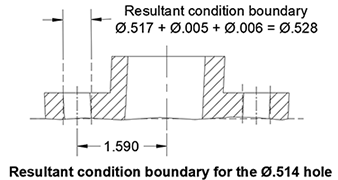
Resultant Condition Boundary: For the Ø.514 in this example, there is primary and secondary design requirements. Since the hole must clear for the Ø.500 pin in the mating part, the hole's orientation and location can be controled with a positional tolerance modified to MMC. This creates an MMC virtual condition boundary that guarantees air space for the mating pin. But now, the wall might get too thin between the hole and the part's edge. To address this concern, we need to determine the farthest any point around the hole from true position (the ideal center). That distance constitutes a wors-case perimeter for the hole show in the right image called the resultant (tổng hợp, kết quả) condition boundary. We can then compare the resultant condition boundary with that for the flange diameter and calculate the worst-case thin wall, then adjust the positional tolerance and/or the size limits for the hole and/or the flange.
Resultant condition is defined as a variable value obtained by adding/subtracting the total allowable geometric tolerance to the feature's actual mating size. Table in Y14.5 show resultant condition values for feature sizes between the size limits. However, the only resultant condition value that anyone cares about is the single worst-case value defined as determined by three factors: 1. The feature's type (internal or external), 2. The feature's size limits and 3. The specified geometric tolerance value.
‹•› For an internal feature of size controlled at MMC: Resultant condition = LMC size limit + geometric tolerance + size tolerance
‹•› For an external feature of size controlled at MMC: Resultant condition = LMC size limit – geometric tolerance – size tolerance
‹•› For an internal feature of size controlled at LMC: Resultant condition = MMC size limit – geometric tolerance – size tolerance
For an external feature of size controlled at LMC: Resultant condition = MMC size limit + geometric tolerance + size tolerance
METHOD FOR RFS (REGARDLES of FEATURE SIZE)
Regardless of Feature Ssize (RFS): It's the default condition of all geometric tolerances by rule #3 of GD&T and requires no callout. Regardless of feature size simply means that whatever GD&T callout you make, is controlled independently of the size dimension of the part.
Method for RFS: A few types of tolerances can only apply in a RFS context. Instead of a boundary, a Level 2, 3 , or 4 tolerance RFS establishes a central tolerance zone, within which a geometric element derived from the feature shall be contained. Each higher-level tolerance adds a degree of constraint demanded by the feature's functional requirement as shown in Fig. 1 through 4.
Your Support Can Help Us Grow. Thank you for visiting ViBa Direct. As part of our commitment to continually improving the visitor experience. I am writing to ask you for your support, such as listing your company here with us. Clearly there is a great deal of manufacturers and distributors including both mechanical and electrical. Unfortunately, I don't have enough manpower to meet everyone needs. But if you are interested in finding out how to support us. Please provide details about your products and reach out to Customer Service, as well as any offerings that you feel may meet customer needs. Thank you in advance for taking the time to read this. Feel free to contact us with any additional feedback you would like to share about your experience visiting ViBaDirect.com.


